January 8, 2015
Continuing work on the cowling and the FWF area.
Here is a view of the final drilling underway on the hinges on the cowling. One of the things where I may deviate a bit from the plans is on the piano hinges used to hold the upper and lower cowlings together. I think it will work to use two small holes in the firewall and insert the hinge pins from the rear rather than the front, and eliminate having to cut openings in the front of the cowling to allow access to the hinges.

Another view of the cowlings with the hinges drilled but not riveted.

And, one more view of the cowling put together. Still rough along the joints but the final shape is pretty much there.

Another deviation from the plans is that I am using CamLoks in place of the two bottom hinges on the cowling. This on the advice of an RV-9 builder who had cracking right here, and the reports of others of the the same problems. Three CamLoks on each side; hopefully, this will prevent hinge cracking that has occurred in this area on other RVs. A mounting plate is mounted on the firewall flange, and a matching plate will be riveted to the bottom of the cowling as a doubler, with the two parts of each CamLok mounted to each plate.

After the hinges were riveted to the cowling halves, I started the long process of preparing the cowling for paint. I did an overall sanding with 80 grit sandpaper. The Van's instructions then recommend using an epoxy blend cut 50% with acetone as a thin layer applied over the fiberglass to fill in the voids and even out the finish. I did apply two coast as suggested but then turned to another method as recommended on the VAF site: basically use full strength or near-full strength epoxy applied and then thinned out with a squeegee to a very thin coat. This was the last coat I applied and it would appear that this will work much better to do the needed prep work. I have not tried to sand this coat yet but expect better results.

So, instead of sitting and watch epoxy dry, I have begun work on the baffles. I got the Van's baffle kit which I think will work out very nicely. The top baffle sections that go to each cylinder are fabricated individually, and I have completed those. They need to be trimmed down to match the top cowling, but this is the starting point.

The next step are the two air ramps that fit on the lower front of the engine and match up to the lower part of the air intakes on the cowling. The left side ramp will also be modified to accept the air filter and then the air box to duct intake air from the cowling intake down to the bottom of the engine at the fuel servo. Lots of stuff yet to do.

January 22, 2015
Work continued over the past few weeks on the engine baffles. I have to say that the baffles have proven to be among the most challenging part of this whole long project. I am using the Van's baffle kit but the kit is one size fits all (RV models) and the instructions aren't all that good, at least in my opinion. Plus, it is intricate and painfully slow at times. Eventually I got past trying to follow the instructions and moved into "make what it needs to be" mode.
Despite the frustrations, the baffles are nearing completion.
Among the challenges is integrating the filtered air box (FAB) into the baffle kit; they don't integrate easily, at least for the horizontal induction engine. The air intake for the engine is placed in the left cowl inlet and is ducted down and around into the forward facing injection servo under the engine. The air intake has an air filter which is mounted on the left baffle air ramp. Things don't fit well together here when the FAB kit meets the baffle kit.
Part of the problem is that there is not as much room in the area as the plans show, so I ended up first building it wrong and then adapting it to adjust to my mistake, and I think it accidently turned out better than it would have if I had followed the plans exactly.
The problem is how the ducting attaches to the ramp; the plans (difficult to discern) have the duct and a mounting plate detachable from the air ramp. I built them as one part. Since these baffle parts have to be installed around the engine, my concern was that the tight fit would not allow the baffle part to actually be installed when it was all completed but it looks like it will work out fine. Pictures are worth a bunch of words.
So, here is the nearly completed air filter mount at the top of the duct that carries the air to the engine intake. The fiberglass duct will end up riveted to this assembly.

And a test fitting of the air filter, still in protective plastic, with the three hold down plates in place.

A view from a different angle. The intersection on the left of this photo between the vertical baffle and the ramp is where there really is not room to fit all that the plans call to be fit together here.

Here is a view with the baffles pretty well put together in a test fitting session. One major consideration is to avoid fitting the oil cooler on the baffle behind the #3 cylinder until after the baffles are cut down in the final fit.

Another view looking aft; the oil cooler will eventually mount on the aft left baffle on the vertical surface, seen on the right side of this photo.

The nearly completed left front baffle with the lower cowl fitted.

And here we are again with the two cowl halves fitted but with the baffles installed on a temporary basis.

So, next is to cut and fit the rubber pieces that actually seal the area between the aluminum baffles and the inside of the cowl, to allow the cooling airflow to be forced around the cylinders and exit beneath and behind the engine. Also, the oil cooler will need to be fitted and installed.
And, to preclude intake air starvation in the event of an iced over or otherwise blocked air filter air intake, I will also install an alternate air source. Essentially, this is a hole cut into the side the air ducting that is covered by a metal plate that can be opened by the pilot (me) to allow the engine to keep running. I have already routed the push-pull control to the cockpit and now need to finish that installation.
Then, finsh the prep work on the cowl for priming and painting, and then move on to the finish the propeller and spinner installation. Lots to do.
February 10, 2015
Moving forward on what seems to be the interminable task of fabricating and fitting the engine baffles. This last part is a bit more complex than the other parts of the baffle. It is mounted behind the number 4 cylinder and the oil cooler is attached to it. There have been reports of the standard Van's baffle cracking at the oil cooler mount so most guys seem to beef up the area. I did too. I added a second full size doubler to the baffle and also an angle reinforcement to the corner where one of the oil cooler flanges mounts. Here are the unassembled parts ready for riveting.

And here is the part after assembly and ready for installation.

I test fitted the oil cooler and checked how to clock the AN fittings to attach the oil lines. I took this photo to help me remember how they were oriented. I used a sealing lubricant on the pipe threads before I permanently screwed them into the cooler.

And here is the oil cooler after it was attached and the oil lines hooked up. I originally used three attach points on the left side of the cooler but the plans only call for two, so it currently has two attach points on each side of the cooler. We'll see how this works out. I also had added fire sleeve 'aftermarket' to the oil lines but was not happy with how the fire sleeve fitted the lines. Hard to fit the sleeve after the lines are built, so I removed it. It would cost a bunch of $$$ to buy new lines with the fire sleeve attached so I will defer that or drop it altogether. I am not convinced on the utility of fire sleeving every line in the firewall forward area. Fuel lines, yes, and they are fire sleeved.

Another view of the oil cooler installed.

So, here is what I thought I was the final configuration of the baffles and shown here ready to attach the rubber seal parts.

Moving right along, I attached the rubber seals in the best way I thought would work. Subject to change. Which it did.

Another view of the baffles after I thought they were pretty much done.

Here is the left inlet in close to final configuration, except what I thought would work for the left and right side rubber seals I later removed and reworked.

As part of the finish-up work for the firewall forward, I installed the alternate air door and cable. This is an emergency procedure to open this door (in case the air filter source is blocked) so it is 'pull the cable to open' process....not a control to open and close the door. Works like a champ for what it is designed to do.

Thinking the baffles were about complete, I moved back to the cowling to do the finish work on it. I had primed it earlier to see where the finish stood and marked areas that needed more work. Also remaining was the oil door.

Ah, the inlet ducts. Part of the airflow control process for engine cooling. So, I knew these were coming and put them in place attached to the inside of the upper cowling. I drilled and clecoed where they should go. Then I refit the upper cowling to the engine and discovered that the forward baffle parts significantly interfered with these inlet ducts. This meant major trimming and fitting of those baffle parts, which meant removing the rubber seals and reworking that whole section. Bummer.

I neglected to photograph the reworked baffle parts but here are the inlet ducts epoxied into place. When I reworked the forward baffles I also reworked the whole air inlet rubber seals on each side closer to what the plans were and also to provide a much better air seal to direct air in manner to which Van's prefers. Cool. Literally.

When I first started working on the cowling, I jumped ahead of the plans and 'over trimmed' the oil door opening. So, I had some fiberglass work to do to correct that error which, I think, actually worked out for the best in the end. The molded oil door insert as provided on the cowling was not 'crisp' in my mind so this might work out better. Here is the set up. I trimmed the provided oil door to size and fit it in the final sized oil door opening. Taped in position, I laid up fiberglass on the reverse side to build up a door flange.

Here is the result of that effort, with some filler added to clean up the new flanges. Should work out just fine. I have a hidden hinge on hand and two spring loaded camlok type latches that will be used to complete the door.

So, I fitted the cowling and started some finishing work. I sanded out some areas that needed more filler and am generally doing preparatory finishing for eventual priming and painting. I have decided that I will use firewall access for the piano hinge wire that holds the horizontal upper and lower cowl joint together. Looks like I can insert with relative ease these hinge wires from the baggage compartment. Not easy at this point, but getting easier as I do it more often and it leaves a cleaner front cowl without the access plates that would otherwise have covered the holes in the cowling needed for forward pin insertion and removal.

I also drilled and mounted the nut plates for the three screws on each side of the inlet ducts. I had had to lay up new fiberglass for these flanges also to get the cowl parts to fit right and there is not much room for the required nut plates. Can't say the final result is my finest work but it should do the job and hold the cowling securely.

As I move forward, I marked out the fourteen screw holes on the propeller spinner at the aft plate, and the six holes at the forward plate, and then drilled some of the holes to start the spinner attachment process. I need to check the propeller fitting to the spinner at different angles, so that is next. I know I will have to do a bit more trimming around the prop cutouts. This is the next frontier.

So, my major immediate goal is to finish the cowling and spinner preparation, and then prime those parts. I plan on having a local auto body shop shoot the final coats of silver paint to these parts and also the landing gear fairings and wheel pants in the near future. Then, with the FWF pretty much completed, it will then move into the next phase: instrument panel and avionics.
February 25, 2015
Over the past few weeks I continued to complete the firewall-forward tasks. As I mentioned earlier, the baffles and cowling have proven to be among the most challenging part of this whole project. I keep thinking I am almost done when yet another unexpected roadblock emerges.
One of the things I did was install the oil door on the cowling. The hidden hinge I had purchased earlier from Avery Tools worked out fine. The two CamLocs latches I also bought from Avery did not. The problem was actually related to the stiffener I attached to the oil door and not the CamLocs themselves, but the result was that I had to change my method of securing the door closed. Not a big deal but it added some fiberglass work to the door (to fill the large hole I had drilled through the door) and find the new hardware for the latches.
Here is the back side of the oil door opening with part of the hidden hinge drilled and clecoed.

And, the other side. The oil door flanges were laid up by me after I had removed too much of the flanges provided already molded into the cowl but I think it worked out better in the end.

Another task was to make sure the spinner was centered properly and not 'wobble' when the engine was running. I am not sure anyone has really had this problem with the spinners now provided by Vans but I thought I should check. Simple enough using a ladder to mount a laser pointer at the tip of the spinner.

In the end, it proved to be sort of a waste of time. I removed the top spark plugs from the cylinders so I could rotate the propeller and check for displacement of the spinner tip from my laser pointer red dot. The dot remained pretty much centered on the tip of the spinner, as expected. After I did this little setup, I drilled the rest of the holes for the screws to mount the spinner.

I then used some scrap 0.050 aluminum to construct the gap fillers for the area behind the propeller blades to fill in the open areas. I used the prop cutout template provided by Hartzell and put the two pieces together.

Here they are fabricated. The two screw holes are where it is attached to the spinner, and the one hole on the tab is where the spinner attaches to the gap filler. The plans call for this to be riveted to the spinner backplate but I decided to use nutplates and screws instead.

So, here is one of them completed and mounted to the spinner backing plate.

And, the same view with the spinner attached. As can be seen, I am using raised screws to attach the spinner to the backing plates. Looks fine to me and is in accordance with the plans.

So, a bunch more stuff happened between completing the spinner and the photo below. Mainly, I finished the preparatory work on the cowl and spinner and applied a two part epoxy primer to the parts in anticipation of final paint.
But, as I did a finalized dress rehearsal of mounting the cowling and spinner, I confess that I am not happy with mounting the two piano hinge pins for the horizontal cowl joints through the firewall from the baggage compartment. The access is limited and the piano hinge pins are difficult to get though the entire length of the piano hinges. I fear that it will result in a difficult to remove cowl, something I don't want to fight with especially in the early days of flying this airplane when the cowling will need to be opened up often for inspections.
I have also spent more than enough time on this assembly. I am going to fiddle with it a bit more but, if not happy, will return to the original Vans plans and cut small slots in the forward cowling through which the pins can be inserted from the front of the cowling. They will be secured to the cowl with a nutplate and screw. Perhaps not as elegant but it will work. More on this later.
Nonetheless, it at least looks like I am getting close with the cowling and spinner, doesn't it? Please say yes.

And, along the way, I also was notified by UPS that they were going to deliver a third propeller to me from my single prop order of last September. For those not familiar with this tale, I received my first propeller as expected in October. I was then delivered a second propeller on Christmas Eve and it took some doing to get Hartzell to correct its mistake and pickup the extra propeller. Then, last week, UPS advised me that it had yet another propeller from Hartzell that was going to be delivered the next day. I managed to head that one off at the pass with the help of Barbara at Vans, and that one was not actually delivered. If this continues I might be forced to go into the propeller sales business.
I am pressing to get the FWF tasks all completed before moving on to the avionics. I'd like to have it 100% completed to avoid having to go back and work on it again. Left to do: resolve my piano hinge issue; torque and safety wire the propeller bolts; seal the firewall with fire sealant; have the cowling painted in its final silver color, and then mount the CamLoc fasteners to the lower cowl. Not too much, but it never seems to be quite finished.
March 24, 2015
Just about a month since I updated this page, not for lack of work but for lack of time. I have made good if sometimes slow and frustrating progress over the last month, finishing up the FWF, getting the remaining fiberglass parts painted, and doing a bunch of avionics wiring. Definitely a learning process, this airplane building thing.
To start off where I left off last time, my experiment to avoid cutting holes in the forward cowl for cowl horizontal hinge pin access did not work out. I could tell I was going to get very frustrated trying to insert and remove the pins from the baggage compartment. So I reverted, sort of, to the original Van's plans and cut holes to allow the pins to be inserted from the front of the cowl...much easier. How to cover the holes, then? Some guys do extensive fiberglass mouldings to create flush hole covers. My patience was not going to allow that, especially since the cowl parts have already been primed. I opted for simple aluminum pieces that hook into the air intake and bend around to be held in place with screws.

Perhaps not as fancy but simple and easy and not too demanding, and won't look all that bad. Done and done and move on to the next thing.

So the next thing was final preparation of fiberglass parts for a trip to the Lincoln Auto Body shop in, not surprisingly, Lincoln. The gents there painted my first batch of silver parts after I was frustrated and unhappy with my efforts, so the second batch is prepared.

This includes the cowling.

And the spinner, which will not actually receive silver paint but will be insignia red, to match the red on the tail stripes on the rudder.

And the canopy, which still retains the sanded down last attempt at me spraying this silver paint. These parts need to look a whole bunch better than what I am apparently capable of with my spray gun paint abilities.

Well, all those parts went off to the paint shop for a week. They came back and they look pretty darn good, but before I move on I shall offer a few comments. I have been using Randolph Ranthane polyurethane paint...two part with a base and a catalyst. The head honcho paint guy made some comments the last time about this paint and how hard it was to work with. He said he could have provided a whole bunch better paint that was much easier to work with and a whole lot easier to shoot.
But, with this batch of stuff, I had already purchased the (expensive) paint and wanted to go ahead and use it. He tried again....had trouble mixing it up (it was well within the advertised shelf life) and it did not shoot particularly well. Some subtle orange peel on the larger stuff. He clear coated it and offered that some sanding and buffing will bring it up to snuff. He demonstrated that process and I think I will proceed down that path with the cowl parts and the canopy. He restated his comments that this paint is very hard to work with, and after his 27 years shooting paint, I think his opinion is worth valuing. He was surprised it could be sold in California as it is quite toxic and, he noted several times, 1940s paint. Okay, I picked up that he was not fond of Ranthane.
Actually made me feel a bit better about the problems I was having. He reserved his comments mostly for the metallic silver...the insignia red for the spinner seemed to work out better and it looks very nice.
Not trying to smack Ranthane; just passing along my experiences with it and those of a seasoned professional used to painting things well. He worked quite a bit trying to get the paint to shoot nicely and it never did...lesson learned for me. I am actually quite happy with the way all the parts came out, but there is that subtle orange peel on the cowl and canopy that I will try and deal with in short order. We shall see.
While all this painting stuff was going on, I moved in another direction, that of installing avionic components. Over the years I have planned and constructed the airplane to accept the Dynon and Garmin and other whiz-bang boxes to add to its capability. Now, how will all this mesh when I actually try and make it work?
Well, the first thing out of the block was installing the autopilot pitch servo and right off it was apparent that the aft control rod bellcrank had two rivets that interfered with the servo installation. A bit of online research confirmed this problem, and offered the obvious solution of replacing the universal head rivets with flush rivets. Okay, then. So, take the bellcrank out and do just that, kind of a pain trying to get it reinstalled with all the washers and such. But I did it and it is done. Word for the wise if you are reading this and planning your RV-8 to use a Dynon pitch servo...these two rivets need to be flush.

I completed the wiring for the Dynon transponder and added the mount to the panel custom built for it. I also added two stiffeners to the panel to beef it up a bit. Seemed a bit wimpy with the ELT and transponder mounted.

And, here is the ELT and transponder installed in place, hopefully permanently.
By the way, along the way, I also repolished the fuselage and installed the two comm antennas and the two DME-type antennas, all on the belly of the fuselage. One of the DME-type antennas is for this transponder and the other is for the ADS-B "in" box that Dynon sells. It will allow UTC access for those non-squitter ADS-B airplanes to display on my Skyview display without an ATC relay. Makes sense, right? Who wouldn't do that?

So this view shows the aft fuselage showing the ELT/Transponder panel on the left, with the pitch servo attached to the aft bellcrank, and also that Dynon ADS-B box on the shelf aft of the pitch servo. All installed and wired. Waiting for me to power them up and then watch them fizzle and smoke.

And, above it all on the upper shelf is the Dynon AHARS box that provide attitude and heading reference, and also pitot-static and temperature inputs into the Skyview system. Needs to be fairly isolated from interference, particularly electrical and magnetic. This location should work. Fingers crossed. Wired up and installed.

In planning the instrument panel, I have to create a wiring harness to connect the Garmin GTN-650, the Garmin SL-40 comm radio, the PMA 5000EX audio panel, the Dynon ARINC-429 box, and the Dynon Skyview display. A bunch of wires come from other places that also connect to these boxes, but this is sort of an interconnect harness that will make 'local' connections. This is pretty important and precise work, but it is also kind of fun. I am using the pin connection spreadsheet I put together last year, doublechecking as I go along with other installation schematics.
So, here is some more advice for anyone doing wiring for the Garmin GTN-650 or the PMA 5000EX audio panel: it is imperative not to use wire gauge larger than AWG 22 for the connecting wires. Why? Because the connectors for these boxes use high-density D-Sub pins that are crimped on the wires. If you had already wired AWG 20 gauge wire for these boxes, you have a problem because the wire is too large to insert in the pins. This is an obvious and easily avoidable problem but for the life of me, I cannot find anything anywhere that states this clearly to the builder planning this out. The Dynon and SL-40 boxes use the standard D-Sub pins so the larger gauge wire is not a problem. There are solutions to the larger gauge wire and the smaller pins but none are easy or cheap or desirable. I replaced some of the wire in this harness I was building and had to order some new wire to use, plus 'adapt' some wires that went into the bowels of the wiring I had already put in. So easy to avoid. Another word for the wise.

Here is some of the wire coming from behind the panel that is completed with pins for installation into the connectors when that 'interconnect' harness is done. The large connector is the 37 pin connector for the Skyview display.

Once I got as much wiring done as I could (waiting for my wire order to arrive from Stein), I turned my attention to the actual instrument panel. I had laid out the basic panel months or years ago, but now redid it very carefully to exactly lay out where the panel displays would go. I needed to 1) mount the avionics stack high enough to avoid the RV-8 fuselage brace that crosses below the instrument panel and 2) not high enough to interfere with the panel backing plate and 3) allow sufficient room between the Dynon 10" display and the avionics stack for the required mounting angles and nutplates and 4) still have the Dynon display centered as much as possible as it is the focus of the flight instruments. I measured thrice and marked carefully.

Then, with a deep breath or two, I prepared to cut the panel. No fancy water saws or laser cuts. This was going to be drills and a jigsaw. It worked fine. Much easier than I expected to cut the holes.

Then, I carefully filed the rough holes to the marked lines, did some test fittings, filed some more, fitted some more, and was happy. Turned out just about right for me.
Looking at this picture, the large hole in the center is obviously for the Dynon display. The large one to the left of it is the radio stack that will contain, from top to bottom, the PMA 5000EX audio panel, the SL-40 radio that will be COMM1, and the GTN-650 navigator. Below that is the opening on the left for the Dynon knob control for altitude, heading, and altimeter setting inputs. My left hand will operate the throttle, radio, and Dynon inputs, leaving my right hand for the control stick. Like I thought this through. Just to the left of the knob panel opening is a small cut out for the ELT monitor. All the way on the bottom right side of the panel is the opening for a USB port for data upload and downloads. Simple panel, the way I want it.
Still a bit uncertain about a backup attitude/heading instrument for IFR flight. It may be the UltraEFIS, we shall see. I have pitot/static plumbing behind the panel for something. Before any hard IFR flying, this will be established, though the Dynon does have a backup battery to power the basic display if power is otherwise lost.

One more thing....my GPS antenna. Like all other RV-8 builders, antenna mounting locations are a bit sparse. Antennas that have to mount on top of the fuselage are the GPS antenna and (should mount to the top) ELT antennas. I have dealt with the ELT antenna at the tail. For the GPS antenna, some guys mount beneath the fiberglass cowl and to the firewall. Works for them, happily, apparently. I am a bit concerned about shadowing from the firewall and would rather stick closer to the Garmin installation specifications. Toward that end, I am going to mount it to the forward fuselage but it has to be slightly left of centerline due to the baggage door. It should be mounted level but, alas, the curving fuselage does not allow this with a flush mount. So, I am experimenting a bit with this idea: a fiberglass spacer that is form fitted to provide a level surface for the antenna mount. It will still allow the antenna to use the standard screw attachments and should not cause any grounding issues for the antenna, nor disturb the ground plane around the antenna. I have no idea of what I am doing but this makes sense to me. So, with some clay and fiberglass, here we go.

Here it is with the fiberglass with some microbubbles setting up. I plan to sand this thing into what is essentially a shim to level the GPS antenna. Stay tuned to find out if this is a viable solution. I am afraid purists and drag-aversion obsessives will wince, but if it works I will be confident in my WAAS signal reception and fly my LPV approaches down to 200-1/2 smiling all the way. I am also going to heed the prominent "Do Not Paint" on the antenna so its shiny white will contrast with the flattened black that will eventually reside on the upper forward fuselage. Won't match: bummer. Still, it should work well to pick up all those little GPS electron things unhindered by metal or paint.

So, this is one long update for something that I suspect few, if anyone, will read, but it important to me to document this process if only for me. And, I can see the light at the end of the tunnel (no, it's not another train coming). This airplane is coming together and years of effort and planning are seeing the light of day. Cool, that's about all I can say.
April 20, 2015
So, another month has come and gone since I last updated anything. This past month has been productive, however, as I completed the airplane wiring, installed the avionics, and fired them up for the first time without major issues. Issues, yes, but not major issues.
So, this is a view of the completed harness of the interconnections between the GTN-650, the SL-40, the PMA5000EX audio panel, the Dynon ARINC-429 box. I did this on the tabletop and then moved it to the airplane to be integrated into the other avionic wiring.

And, here it is integrated into what are essentially complete harnesses ready to be attached to their respective connectors on the boxes.

So, the next step was to fabricate the avionic rack that will contain the stack of three radios. I worked hard to fit them properly so the depth would allow the front pieces to be even and to ensure the boxes would be fully seated in the racks and, thus, make complete contact with the connectors in the rear. Turns out I did not work hard enough, but more on that later.

A front view of the panel with the radio stack clamped into place just prior to drilling holes.

The front of the radio stack is mounted to the instrument panel. The back of the stack needs support, however, so I used aluminum angle to construct a tray that bolts to the bottom of the GTN-650 rack that, in turn, supports the other two racks. Simple and relatively easy to install despite the close quarters.

Here is the radio stack being test fitted with the connectors attached to their respective racks. I knew it was going to be tight but was surprised at how much the harnesses extended forward of the access panel cut into the bulkhead that separates the instrument panel area from the forward baggage compartment. Those bundles are stiff, too, and it would require some rearranging of the bundles to make it all fit.

Jumping ahead a bit, here is a view of the panel permanently installed and operating. On the left stack, from the top, is the PMA5000EX audio panel, below that a Garmin SL-40 acting as COMM1, and below that, the Garmin GTN-650 navigator with RNAV LPV capability and a "legacy" VOR/ILS receiver to boot. Below that is a Dynon knob controller that inputs into the Skyview screen (inputs barometric altimeter setting, and heading and altitude inputs for the autopilot). The small panel to the right of that is the ACK ELT panel. The main display is the Skyview 10" touchscreen.
The big hickup I had was with the audio panel. COMM1 receiver was intermittent and did not produce sidetone, and the transmit function from the front stick was missing. I thought I had mis-wired something so pulled the audio panel back out and surgically opened up the J1 connector, as that is the one that controls the front stick 'push to talk' inputs. At first it appeared I had put some wire pins into the wrong holes in the connector. After I reworked three pins, I figured out I was looking at the connector backwards and I had been correct in the first place all along, so I redid that work again. I put it all back together but had the same problem. That is when I figured out that the audio panel was not seating all the way in the rack. I ended up redoing the upper rack and moving it forward a quarter inch. After all that, which took several hours by the way, the audio panel worked fine.
I did some basic set up on the Skyview and GTN units and, in short order, everyone was talking to everyone else via either the ARINC box or serial cables. It is all pretty impressive to see what this avionics 'suite' is capable of.

And, I was getting excellent GPS satellite reception in my garage, including an LPV level navigation solution. I played around with my fiberglass spacer that I had earlier fabricated for the GPS antenna and found no difference with the spacer in place or missing. That, and a good discussion with one of my Oklahoma City cohorts who had spent a bunch of time working with GPS antenna shielding issues during early LPV development, and I am confident I can install my GPS antenna without the space. Won't be exactly level, but the airplane won't be exactly level all that often either.
So, here is the fuselage in a very nearly finished state. I added the six camlocs I am using to replace the hinge pins on the bottom of the lower cowling, and put the top cowling on just to take a look. Looks pretty good to me. This thing is getting close.

I am moving into the clean up stage. I have a list of things to do, and am moving through that list pretty quickly. I am going to be otherwise occupied for a good part of May, but expect that June will find some final assembly and a move to a hangar at Lincoln Airport all in the offing.
June 4, 2015
Six weeks since I last updated. Bunch of stuff going on including three weeks in France on vacation to see my son get married and other stuff. Cool. But, back at it off and on as I start wrapping up the construction of the RV-8. I had a list of odd ball leftover stuff that needed to be done, and I worked my way through that list.
Among those items, I had waited to torque the propeller nuts until I went to plan B with the special propeller wrench. I completed the torqueing and then added the safety wire to each pair of the six nuts.

After all the work was completed on the propeller, I did the final attach of the propeller spinner. Done and done.

Another item to do was to install the RAM mount to hold an I-Pad Mini that will be my chart source when I fly. Three screws to hold the ball mount inside on the right side of the cockpit. Primed and finished. Works well.

I had some final painting to do on the area forward of the canopy, between the windscreen and the cowling. the paint went on well enough, though the final result was not quite as good. It was dusty and that did not help, but it turned out well enough.

After unmasking, here is the final result. Sort of an anti-glare panel except it is glossy so it will glare. I had some flattener I was going to add to the paint but ended up changing my mind. I'd rather have the gloss.

And another view. This about takes care of all the painting on the airplane, thank goodness. Paint was not my friend.

So, I moved on to installing the stabilizers and tail control surfaces. Looks good to me.

Another view. Since I had installed the tail section earlier and had pretty much set these parts. I had to make some final adjustments and the rudder had to be pretty much reworked entirely. Also, the right side elevator counterbalance to the horizontal stabilizer had insufficient clearance. It is supposed to be 1/8" clearance. I ended up sanding down the fiberglass tip on the horizontal stabilizer to increase the clearance. Another little time consuming project as I move along.

In sitting in the airplane with the rudder hooked up, I was not happy with the geometry of the rudder pedal extensions. Too much bend and it was a weird angle for my feet. So, I removed them and have set them aside. I'll fly it with the standard RV-8 rudder pedals and may modify these and reinstall them later.

Here is ELT antenna installed. This is an ACK 406 antenna and it is installed in about the only place where it works.

And here is the VOR/Localizer/Glideslope antenna mounted on the top of the vertical stabilizer. I mounted it forward to minimize interference with anyone walking around the tail section.

And, I added this placard to the aft cockpit on the right side, a required item for an Experimental airplane.

And, the FAA assigned my reserved tail number to the airplane, so it only seemed appropriate to go ahead and apply the vinyl N number I ordered months ago. The came from FlyBoy Accessories. Worked very nicely.

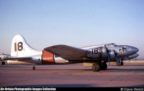
So, the tail number? Why is it special? Well, it was once carried by a civil B-17 air tanker that had a little accident and has been out of service for four decades or so. I've been a B-17 aficionado for four or five decades myself, so I thought it was appropriate to carry forward the legacy of that old B-17.
June 18, 2015
A red letter day in the construction of an airplane is when it finally gets to move to the airport. Well, in my mind anyways. Not sure that applies to Boeing 787-9s but I know it does to kit built airplanes. And, I am happy to report, RV-8 N9324Z made that journey last Saturday, one June 13, 2015, quite successfully, and it now sits in a hangar at the Lincoln Municipal Airport. All this thanks to a bunch of folks who lent their time, muscles, minds, trucks, and trailers.
A bit of back story here. I did not have a hangar on the prior Thursday morning despite a good deal of effort and some prospects. But, by Thursday night I had secured a spot in a large hangar to be shared with four other airplanes (being two Pitts Specials, a Cessna 170, and a Piper Tri-Pacer). Also by Thursday night my son Adam had worked out the borrowing of a large car transport trailer from his neighbor, somthing that required the neighbor to remove side panels from the trailer, and Adam allowed me to borrow his 'classic' pickup truck. Thanks to Kenny and Adam... And, I was able to enlist the help fo a number of people to bring some muscle and expertise into the project, all set to begin on Saturday morning.
So, here we are starting on Saturday morning. If you ascribe human emotions to metal, this RV-8 is eagerly awaiting its day in the sun. If you don't, well, it is just sitting there. I guess I fall in the latter camp, but it sure looks good, nonetheless.

But, into the sun it went. And here we are muscling the fuselage onto the trailer. Not real hard but also real close to disaster if something starts rolling the wrong way. Fortunately, it did not. Fellow EAA Chapter 1541 member Bruce Estes has done this a few times, so he helped us novices keep things straight, literally. Photographer and interested aviator Bill Reid took a whole bunch of photos, including all these on this page, and also pitched in when needed to move something when something needed moving. Also, my son Lucas and his wife Ginger and my wife Lisa all added brawn, brains, and beauty to the whole thing. I'll let you all figure out who did what there, but all pitched in a bit of something mixed and matched.

And here is the whole group breathing a sigh of relief after the fuselage was securely on the trailer and ready to roll.

So, off to the airport we went. I took the back roads to get there and kept it nice and slow. The county roads around here are extraordinarily bumpy, the standard for Placer County it would seem, so I really had to slow down in some parts to keep the jarring to minimum. But, we pulled into the airport, a caravan of about four cars led by a white pickup pulling this RV-8. Cool.

If loading was dangerous, unloading is really dangerous because it does not take much for the airplane to move the wrong way once it gets going. We were careful and took it slow and it was a non-event.

All that was left to do was to roll it into the hangar and then go get the wings.

My son Adam and his family had another commitment which is why they were not pushing and pulling on the airplane with the rest of us, but they did have to stop by and see the progress we were making. They have two incredible kids and this is the oldest (Clarence) thinking about learning to fly someday.

So, then it was back to the garage to load the two wings onto the trailer. A bit easier than the fuselage was but we had to be careful to secure the wings so they would not shift. Awkward shapes don't lie together well.

This first attempt does not look too stable so we shifted it and spread the wings to each side of the trailer. Well padded, they were ready to travel.

Back at the airport, we unloaded the wings. I wanted to take advantage of the many hands to pin the wings on with the drift pins I made last year when the wings were test fitted. I got a bit ahead of myself here and did not properly set up those items between the wings and fuselage (wiring conduit, fuel lines, etc.) and I paid for that a bit later with some extra work, but in the end it worked out okay.

Bill Reid shot this cool view of the tail in the process.

And this was the end of the morning....N9324Z sitting basically assembled in its new spot in the hangar. Moving day is over and it was a success.

So, now I need to proceed to the next step, that is permanently securing the wings to the fuselage with ten, count 'em ten, bolts on each side. Some big, some little, all a bit hard to reach. Then, fuel lines and electrical wiring from the wings need to be hooked up into the fuselage, and then the ailerons and flaps installed. Then more stuff. Lots to do. Always lots to do. But, a bit step now safely behind.
July 15, 2015
It has been a busy few weeks as I press forward with finishing the RV-8. Many small tasks have been accomplished, and a few bigger ones. The airplane is essentially finished. All the aircraft systems have been completed and operationally checked. In no particular order, then, the past few weeks:
Fuel System
- The wing to fuselage fuel lines were connected and a leak check completed.
- The fuel tanks were calibrated with the Dynon Skyview fuel gauges. This required filling each 21 gallon tank, 2 gallons at a time, and electronically marking each 2 gallons in the Skyview system.
- Fuel flow tests were completed with the aircraft in a flight attitude. For details, this Lycoming IO-360-M1B engine requires being fed at a maximum rate of 87 pounds of fuel per hour at 100% power. The standard expectation is that the fuel system shall feed at a minimum of 125% of the required fuel flow for a pressure fuel system (with fuel pump vs. a gravity system), which equates to about 108 pounds per hour which equates to about 18 gallons per hour, or 0.30 gallons per minute, or about 38 ounces of fuel per minute. Okay, I can measure that. I ran fuel through the system from each tank through the aux electric pump and measured at the engine pump inlet: both sides fed at 108 ounces per minute, or almost three times the required.
- I also determined the unusable fuel in the flight attitude to be negligible, or next to nothing...perhaps a few ounces.
Electric System
- All the electrical connections between the wings and fuselage were made. Most of these had already been hooked up and checked, but they were finalized and checked. This would include nav and strobe lights, the aileron autopilot servo, the pitot heat, and the fuel sending units.
- I found two wires that had pulled out of a connector in the fuselage...both of them were ground wires for the elevator and aileron trim servos, so I reconnected them with soldered connections...probably a lot more reliable of a connection.
- The wing temperature probe wiring was installed from the wing back to the Dynon AHARS unit.
- The flaps and ailerons were reinstalled for, I hope, the final time.
- The aileron push rods were hooked up to the control system in the fuselage, and they were adjusted and rigged in the wings. I had concerns about the aileron push rods and some electrical wiring in the fuselage in the area where they entered the fuselage and, it turns out, for good reason. I had to adjust several wire bundles in that area to eliminate the interference.
- The flap motor and associated push rods were installed after the rear floor was installed, and the flaps calibrated with the Dynon Skyview.
- I did a final check of the flight control rigging and measured the deflections of the ailerons, rudder, elevator, and flaps after their final installation.
Interior
- Did a final install on the rear floorboards, and several panels in the forward cockpit were screwed on for what might be the final time, though I've already taken one back off.
- The forward floor boards were installed, but they will be coming back out later for inspection purposes.
- Seats and other interior stuff were fitted, somewhat permanently.
- My Crow five point seat belts were installed and adjusted. To fit. Me.
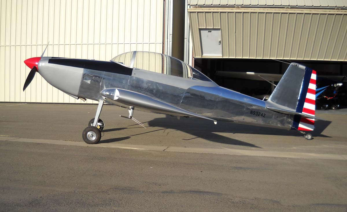
- I did a complete assembly of the aircraft to get it ready for weighing. All components were installed. This gave an opportunity for a first completed view of N9324Z:

- Looks pretty good to me. I did decide to extend my black glare shield markings forward onto the top cowling, sooner or later. A bit more paint (later), but it will be a better result (later). Okay, then.
- With the assistance of several very helpful individuals, we weighed the RV-8. Result was an empty weight of 1,136 pounds with a CG of 78.07 inches aft of the datum. A tad bit heavier than I had hoped and with a pretty far forward CG, as expected. That's not bad, though, as almost all added weight (fuel and passengers) are aft of that CG and will shift the loaded CG aft. Usable load will be 664 pounds. With full fuel (42 gallons x 6 pounds per gallon or 252 pounds), that leaves about 422 pounds of pilot, passenger, and/or baggage.

- Yep. Several times, actually. The unofficial first engine start and then the First Official Engine Start.
- With the help of one able and knowledgeable individual (thanks, Bruce!), we did the unofficial first engine start on a quiet Saturday morning quite in solitude. Pre-checked everything several times and then found, first, one good oil leak and, then, several good-enough fuel leaks. Among those fuel leaks were the fuel injectors going into the engine itself. I had checked the injector lines going to the injectors but figured Lycoming knew how to tighten the injectors themselves. No, I guess not. With all ship shape, or hopefully so, I cranked the engine with ignition wires attached and a magneto hot for the first time, and the thing fired up, pretty rough at first, but soon enough settled down into a nicely purring Lycoming engine. Bruce, standing back and watching carefully for more leaks or other even worse things, noted it blew a bunch of oily smoke for a minute or so, not surprising given the residual bit of Lycoming pickling oil still in the engine intake and cylinders. Not quite B-25 worthy, but it will have to do.
- I ran the engine for several minutes below 1000 RPM, as per Lycoming instructions, then ran it up to about 17 inches of manifold pressure and cycled the propeller RPMs several time. It took a few times, but the oil eventually got through the propeller governor and the prop RPMs cycled as expected.
- I did a magneto check at 18" or so and noted the left mag did not drop RPMs, and after the right magneto did it once, it did not drop again. Hmmm...
- Back to idle, I checked the magneto grounding to make sure the mags were properly grounded. Turned out they were not. Hmmm...
- I planned the "Official First Engine Start" for later that day, and ended up spending quite a bit of time, with no satisfaction, with correcting my magneto wiring. I knew I had a hot prop and took appropriate precautions until I did get it straightened out.
- Later that day, I did have the "Official First Engine Start" with some interested friends and family in attendance. Cool. Engine started again and ran quite nicely, thank you.

- Mags still did not work as intended. Hmmm...
- But, the after-start barbeque was quite good, thank you very much.
- The next day, I calmly sat with my wiring diagram, my AeroElectric book, my electrical tester, and my magneto wiring and straightened it all out. Put it all together, and ran it again. Worked as advertised. Magneto checks were within expected values, and the magneto grounding check was satisfactory. Good to go, with the mags, anyways.
- And, by the way, I did check for any noise coming through the radio receivers from the Aeroled nav/strobe lights and/or the engine running. Not a bit. I guess following the instructions for grounding the lights and magnetos worked. Who would have thought?

More Stuff
After all was said and done, my list is getting shorter of things to resolve and/or do:
- The brakes need a bit more attention. I have a bit of a leak on the left brake and want to make sure the lines are air bubble free with a final bleeding.
- I need to check my alternator as the Skyview electrical system readings are not giving me the warm and fuzzies I was expecting. I did a bit of research while away from the airplane this week so I have a plan to verify my output and Skyview readings.
- My ACK ELT and Garmin are not talking yet. I need to introduce them to each other.
- I think I am going to adjust my avionics master switch wiring a bit and take the Dynon Skyview off this switch. I think I want the Dynon powered up with the battery master switch instead. I need the engine gauges for engine start and the Dynon is designed to handle the electric surges that occur during the start. This change should be straightforward on my breaker panel.
- I need to calibrate the autopilot and autopilot servos.
- I need to get a static system check and a transponder certification check...both required by Federal Aviation Regulation every 24 months for airplanes that use the 'national airspace system'. That will be me. An avionics shop needs to do these checks. I have one scheduled.
- Assemble my airframe, propeller, and engine log books with proper entries and documentation, plus do all the little paperwork shuffle things to make the FAA happy. And I want the FAA to be happy.
- Complete my airworthiness certificate application package and get it submitted to the FAA FSDO office for scheduling an airworthiness inspection.
- Other stuff I don't even know about yet, but will shortly.
So, getting much closer to flying this airplane. I hope to do some transition training in August and then fly, finally, in late August. We shall see.
August 31, 2015
I have neglected keeping my progress up to date but here is the gist of the activity since the last update in mid-July:
All activity was centered to my airworthiness inspection that was initially scheduled for early August, then moved by schedule conflicts to the last week of August.
After a successful inspection conducted by a FSDO airworthiness inspector on Wednesday, August 26, I moved forward to making the airplane's first flight.
That first flight occurred on the morning of Sunday, August 30, 2015, and was also successful. So, now RV-8 N9324Z is officially an airplane, and it has taken to the air.
So, now some details.
Through the last two weeks of July, I worked through my list of 'to-dos,' until it was a very short list. Among the items I addressed were some mentioned in my last update.
I did rework the avionics master switch and took the Skyview off the avionics bus and put it on the battery bus. So it is now powered when the battery is on, so I have engine instruments during engine start. I also figured out that my Garmin GTN-650 was indeed feeding a GPS position to my ACK 406 ELT as it was supposed to. Took some effort to establish that, but established it I did.
I had my pitot-static system checked by Jon of Precision Static Testing out of Livermore, California. Excellent service as he came to my airplane one Sunday morning (fit both our schedules) and he gave the pitot-static system and the transponder some close scrutiny and few adjustments and some paperwork to go with it.
I was able to schedule my airworthiness inspection with FAA inspector Richard 'Dilly' Dilbeck out of the Sacramento FSDO office. He takes a great interest in experimental amateur built airplanes and added his expertise to the process for me. We had scheduled for August 10 but then we had some schedule conflicts, and rescheduled for August 26. Good enough.
In the interim, I did my transition training with Mike Seager. Mike is well known amongst the Van's crowd providing a bedrock of transition training for those new to the RV airplanes. He is based at a small turf strip (05S) at Vernonia, Oregon, about 40 miles northwest of Portland. I spent almost 10 hours of flying with him over three days in mid-August. We flew his RV-7 which is pretty close to an RV-8 (only one number different). He was working with another pilot doing transition training for the RV-10, so that was also going on. Mike will provide training in any of the Van's stable of airplanes. Most of the transition work revolves around takeoffs and landings, and much of that was done at Scappoose, Oregon (SPB), a nice little airport downstream (as the Columbia River flows) from Portland. Weather was Oregon good, thus sunny, cloudy, rainy, windy, and calm all in the same few minutes. A special treat was flying from the turf strip at Vernonia, especially the 'sporty' arrival to runway 27 that features a curved approach through a little opening where the trees had been, just for that purpose, removed. An "E Ticket" ride for you old Disneyland types.
I'd like to say I did great but, well, it was interesting. I had not flown a 'light' aircraft for at least a decade. The light weight and sensitive controls were the recipe I needed for overcontrol, something I was expecting and was not disappointed. But, it came along well enough. The tail dragger thing also came along slowly. My tail dragger experience is limited to a bit of Citabria time and a hundred hours in a DC-3. The DC-3 is to the RV-7 as the eighteen wheeler truck is to the Porsche. But that is why I wanted a tail dragger. We shall call it developing a new skill set. Mike was patient and helpful and by the end of the flying I wasn't scaring him too much.
In the intervening weeks in August I had to actually work for my employer, and that included two weeks flying in Alaska. Lots of stuff going on.
But, on Wednesday morning (August 26), FAA Inspector Richard Dilbeck came out to the hangar at Lincoln (LHM) and spent the morning giving N9324Z a close look. He found some stuff that I had overlooked, including a couple of missing cotter pins that surprised me. How I missed those is hard to figure, but he also showed me some techniques and 'best practice' stuff that I have since incorporated. At the end of the morning I had my 'pinkish' airworthiness certificate. The airplane was now an Airplane. A big milestone. Cool.
It was, however, somewhat disassembled for the inspection, so I had more stuff to do. Plus some clean up items after the inspection. Always more stuff. So, over the next few days I did all that stuff. All the inspection panels and the fairings and the floors and the seats and all the other things were reinstalled. Then I started checking everything twice, because I could tell that this was soon going to get serious.

Serious in that I was going to fly this airplane. So, I was going to test my ability to turn a pile of parts that showed up at my house into an airplane. And I was also going to rely on a brand new engine and a brand new propeller to work, if not flawlessly, pretty much flawlessly. And, I was going to test my own ability to fly an airplane type I had never flown before. Now, granted, this is not an unheard of challenge. People out there are doing this every day, flying brand new kit built airplanes that they have carefully constructed and learned to fly. But this was getting personal, so I took care. I decided my first flight was going to be 'unofficial' so I could have a low key experience with the pressure of an audience. So, I planned an 'unofficial first flight' for Sunday morning and my 'official first flight' for late afternoon on Sunday.
The airplane was ready Saturday afternoon, so come Sunday morning it was pretty much roll it out of the hangar and go. More to it than that, though. I did have a few in attendance, and a bit of help from a fellow EAA chapter member (thanks, Bruce!). I took my time and did a careful engine runup and then a slow taxi down half the runway to check brakes and how it handled. Then, back to the approach end for real.
I lined up on the runway and pushed the throttle up. I was still adding power and brought the tail up just a bit when the RV-8 sort of leapt of the ground. It was more than ready to fly. I was a bit startled by how fast it came off the ground. The RV-7, with 20 less horsepower and two big guys in it, had a ground roll. This RV-8 was flying way ahead of me. I managed to catch up pretty quickly, though, and turned out of the pattern toward the east of Lincoln, climbing up to 3500'. My plan was to orbit just east of the airport, just in case, and fly at wide open throttle (WOT) to try and seat the piston rings as soon as possible. So, I set my power and pulled the propeller back to 2300 RPM, let myself breathe a bit, and started to get to know the airplane a bit. It is surely a sweet flying machine; very sensitive about all the axis, as expected. Visibility out of the bubble canopy was incredible. I watched the engine gauges carefully...cylinder head temperatures were the main ones to watch, and they were, as expected, pretty high, from about 390 to 425 degrees F. Everything else was pretty much where it should have been.

I motored about for nearly an hour, boring circles in the sky and trying turns in both directions, some climbs and then some descents, all with WOT. In level flight, my indicated airspeed was in the 150 knot range but I was burning a bunch of gas at that power setting, about 15 gph.
After an hour, I let down back into the pattern, trying out some speed reductions and slow flight on the way down. I flew a normal pattern and it was a pretty stable approach with full flaps. I carried too much power too long and the airplane did not want to land. I was not happy with where things were going so went around. I did that one more time, before I finally got the power to idle early and made an acceptable, barely, three point landing. All told, the first flight had a high pucker factor, but I think I had the trademark RV grin on my taxi in.

I was pretty happy and everyone else who was there was pretty happy with the whole thing, or at least seemed to be. We rolled it back into the hangar and went off and did some other stuff for awhile.
I came back a couple of hours and pulled the cowling to check stuff out, and did another careful preflight. I taxied to the fuel pumps and added some fuel. Then, at about 5:00 p.m. under perfect conditions...clear skies and no wind...flew the airplane for its second flight. I had friends and family gathered this time...and I was much more relaxed this time around.

Beautiful evening to fly and the landing worked out very nicely, all things considered. Added another half hour of flight time to the airplane. It was a picture perfect end to a good day of flying, and then we had some pizza to boot.

So, after two flights, I have some things to correct and some things to adjust, but nothing major. The airplane seems to fly pretty straight, and I can tell it will be just what I was hoping for in a sport airplane. I look forward to many years flying this airplane both by myself and maybe also introducing some others to flying and aviation.
Yep, this is my new favorite picture. It shows my grandson Arlo eyeing the RV-8. He seems to have a particular affinity for airplanes...gets a bit excited when seeing them. I'd like to think a future pilot...we shall see.

So, by my account, this airplane took about six years and eight months to build. How many hours of time? No idea, but a bunch more than the 2,000 some talk of. How much money? A bunch...probably 20% more than I thought. But, the RV-8 is equipped as I originally envisioned, and worth every penny in my book.
I wrap up this building experience and reflect that it has been pretty much all positive. I learned a bunch, had some help from some pretty giving people, and ended up with a good airplane in a hangar.
I'd like to make a complete list of people who helped me build this airplane, but know I would leave someone out. Some helped with riveting, some with knowledge, some with encouragement, some with skill. A short starter list needs to be documented, though....Lisa and Adam and Lucas and Nathan and Bill and Greg and Kevin and Duc and Michel and Ed and Bruce and Dan and Keith and Tony and Stan. And to Doug Reeves and his Van's Air Force website and the information resources available there. And to 'Van' himself, that would be Richard VanGrunsven, who designed some great airplanes and started a company that has changed sport aviation.
So, though a bit long winded and a bit too wordy, this wraps up the construction of RV-8 N9324Z. On to the next thing...owning and operating an RV-8. Cool.