Working on FWF items, particularly wiring to hook up sensors and accessories.
Here is the 6 AWG wire from the ANL current limiter to the alternator, bundled with two other alternator wires and some EGT and CHT engine sensor connections. To be added: a standoff from an engine bolt to position the wire bundle a bit better.
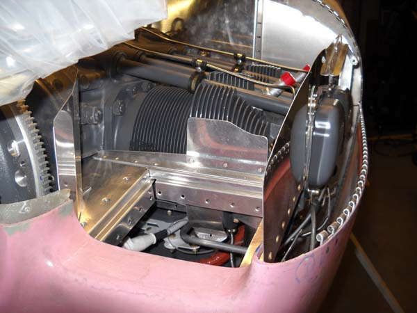
The other end of the alternator wires, the big one going to the current limiter at the bottom of this photos, the others joining the wires from the manifold pressure sensor, and the whole group going across the top of the firewall.
Here is a view of wire bundles coming through the firewall and going up to several of the engine sensors. Not too exciting but necessary to hook up all the sensors to the Engine Monitoring System.
Here is a right front quarter view of the engine with the #1 cylinder EGT hooked up. It and all the other EGT sensors are installed 3.75 inches from the cylinder exhaust port. As instructed by Dynon (and others), they need to be a standard distance from the cylinder to provide the most accurate information. Behind that exhaust tube is the heat muff attached to the #3 exhaust tube. Coming together slowly.
In the coming weeks, I hope to complete the FWF installation of wires and exhaust and accessories, and then move on to baffles and cowlings.
December 18, 2014
I continue to make progress on the Firewall Forward (FWF) installation and, at this point, am nearly complete with the engine and accessory hook-ups.
Here is the left side of the engine with the spark plug wires in position. Sorting out the spark plug wires took a whole lot longer than it should have for one simple reason. Neither the Lycoming manual that came with the engine nor the Van's instructions for the FWF had an accurate diagram that shows the magnetos and wire runs correctly. You have two sets of wires, one for each of the two plugs at each cylinder and they are routed either to the top plugs or the bottom plugs. If you try and go by either set of provided documents, you will probably end up confused and with a bunch of wires that are too long at one place and too short at another. As a start, my Slick mags are standard mags probably come with all the new Lycoming 180 engines. All the magneto diagrams are 180 degrees out from where the #1 spark plug wire is positioned, so the subsequent wire runs make no sense. The Van's instructions mirror the Lycoming information, but it is less complete in its incorrectness.
So, for anyone reading this, here is how I learned the obvious. Perhaps it is common knowledge but it escaped me and did not appear in any of the postings I found on the VAF site about this topic: the correct cylinder for each plug wire is stamped on the connecting fitting for the spark plug. The #1 cylinder top plug wire is stamped "T1" and the bottom wire is stamped "B1", etc. etc. Knowing this ahead of time would have saved me a bunch of time and effort. Again, perhaps it is obvious to all except me but if not, knowing this ahead of time makes it all easy. Enough said.

Right side view of the firewall with the braided hose going between the manifold pressure fitting on the #3 cylinder and sensor on the firewall.

I decided to add firesleeve to the oil cooler hoses and the fuel pressure hose and the oil pressure hose. A bit of mixed feelings on this as I am not sure if it is that necessary, but it is commonly done so I went ahead and did it. The raw ends of the cut firesleeve needs high-temp protection of some sort to make the firesleeve effective. You can goop it up with high-temp Permatex silcone, or you can use high cost dipping material to dip the ends, or you can do what I did: make homemade dipping material from Permatex silicone.

Not my idea but, as usual, comes from the invaluable source at the VAF forum. Basically, you mix the Permatex high-temp silicone with MEK to the needed consistency, then dip the hose ends in let it set up. Worked like a charm. I mixed it in a container, then poured it in this high-tech Dixie cup, and dipped away. The liquid to the left is not for dipping but for staying warm in the brisk 60 degree Sacramento winter environment. Brutal and even raining.

Knowing that only the strong survive such adversities, I pushed forward and here is the result. Works about as well as using a can of the high priced dipping stuff but for the small number of hoses I had to do, it was the ideal solution. Once again, the invaluable resource that is Van's Air Force forum site. How did it get done before?

Here is a view from on high of the left magneto hookup. The P-Lead has the grounding lead split off and going to the grounding terminal. The green tape on the magneto is left over from me trying to figure out the plug wires. It is, according to the Lycoming drawings, the #1 cylinder but it is actually not.

Here is the left side of the firewall wiring coming together. You can see the "red cube" fuel transducer hiding in there, awaiting one custom hose to be received. I'll write on that a bit later after the installation is completed for the fuel lines. I'm trying to keep the whole thing neat and organized. We shall see.

I used the exhaust mounting hardware that came with my Vetterman's crossover exhaust. It is basically a pair of tubes that extend from the individual exhaust pipes to connect to bolts that hold the oil sump to the bottom of the engine. Thus, it is mounted to the engine and not to the engine mount, allowing the engine and exhaust to vibrate in unison. Four inch sections of rubber hose act as a shock absorber to the mounts, bisecting the tubes.
However, I don't see how it could work on the RV-8 without some sort of adjustment as the geometry interferes with the exhaust. I made it work by using two-inch extensions to the tubes at the oil sump end. Here are the two tubes coming down from the engine to the exhaust pipes, with the clamped rubber hoses installed.

As per the Van's instructions, I installed some firesleeve on the throttle cable that runs between the bottom of the engine and exhaust system. Not seen here is a heat shield also installed to protect the throttle cable.

The oil breather hose installed at the top of the engine. Lots of discussion on the VAF site about the oil breather, particularly with the pros and cons of using an oil separator to keep the bottom of the airplane clean and possibly boost engine performance a bit. I think I will stay old school and stick with the boring installation as per the plans.

For now, then, this is how the bottom end of the oil breather tube is installed: right over the left side exhaust pipe. The idea is for any engine emission to drip down on the pipe and burn off, keeping the bottom of the airplane clean and shiny. Well, we will see, but this is simple and pretty fool proof. However, note also the small relief hole drilled into the side of the tube visible just behind the engine mount. If, for whatever reason (i.e. ice or gunk), the bottom end of the breather tube gets blocked, the internal engine pressure has to go somewhere and it usually blows the front oil seal out of the engine. That is not good. Thus, the relief hole.

So, while awaiting a bit of hardware to arrive from my friends at Aircraft Spruce, I moved on to the propeller. First off is the preparation of the spinner backplate. This backplate is used for both fixed and constant speed propellers, but the mounting configuration is completely different. For the constant speed installation, the backplate has a doubler attached to the rear, and that doubler is also used as a pattern to remove the center mounting holes and material from the backplate. This is because the spinner backplate is mounted to the propeller and not the engine flange.

So, after using a cut off wheel and a die grinder and a bunch of files and sandpaper, here is the backplate in its required configuration.

A bit later after priming and riveting the doubler to the backplate.

So, ready for installation along with the forward mount for the spinner which is mounted directly to the forward end of the propeller hub.

And, here's the baby out of the box. A brand new Hartzell 72" constant speed propeller ready to take me places.

The spinner backplate is thus mounted to the rear of the propeller to four bolts. The nuts on the bolts come fully installed and torqued, so the locking nuts need to be removed to allow the spinner to be installed. The Hartzell instructions specify to install with new, yep, new nuts, implying that these are one-time nuts to be discarded after being used once. Not so, according to Hartzell upon inquiry. These nuts can be reused. The instructions are a bit outdated.
And, after the nuts are installed, they are torqued to 22 foot pounds, dry torque that is, as per the Hartzell manual. So, you might ask, since the torque drag on the locking nuts is almost 10 foot pounds, should this be added to the 22 foot pounds when they are torqued down? This makes a big difference. Well, fortunately, Hartzell is quick to answer questions because the book value provided is, it turns out, the final torque value. Torque drag is already considered with the number given. Okay, then.
As an aside, it sure would make sense if the instructions for engines and propellers and airframes would just make it easy and specify the final torque value or make it clear when it isn't. The torque drag of locking nuts is not a constantly changing thing; just include it like, well, like Hartzell does, but specify that it is the "final" value. Saves questions asked and answered. Just an aside.
The big orange disc in the middle is soon removed. It covers the large oil passage that marries up to the crankshaft that, in conjunction with the propeller governor, actually changes the propeller blade pitch to maintain a given engine RPM.

Getting ready to install the propeller, at least on a trial basis. I ended up rotating the engine a bit to line up the flange with a level propeller to make the installation easier. Since the engine has preservative oil in it, I removed the top spark plugs before rotating the crankshaft. I would hate to start bending connecting rods on a new engine.
Not a good view, but at the center of the engine flange, one can see the round opening that marries up to the back of the propeller hub. When the engine was received from Lycoming, a metal plug covered this opening. If a constant speed propeller is to be installed, that plug is removed so oil can flow to the propeller hub as Hartzell intended. I removed and discarded the plug. By the way, a second plug further down the hollow crankshaft is left in place for a constant speed propeller but pierced (or removed) if a fixed pitch propeller is used. Basically, when set up for a constant speed propeller, a cavity is formed in the hollow crankshaft and adjoining propeller hub that allows the governor to adjust oil pressure in the cavity to control the blade angle and, thus, engine RPM. Those engine/prop guys are pretty smart.

The propeller installed on the engine, with the front spinner mounting plate also installed. I had to get the propeller on the engine so I could properly install the cowling. Guys talk about the propeller going on and off the engine a few times before the final installation but, for the life of me, I can't see why I would want to take it off again. Maybe it's a constant speed thing...

As can be seen, there is good access between the starter ring gear, the prop flange, and the spinner backplate, more than enough (I think) to do the spinner work. The six flange bolts are tucked in there between the spinner backplate and the flange, and it will take a special tool to torque these properly. So, for now, they are just past finger tight.
Note that, in a stroke of unusual planning, I managed to get the alternator belt on the alternator before installing the propeller. Usually it goes the other way and I would have had to start over and take the propeller back off to get the belt on. Sometimes I get lucky.

So, here we are with the propeller installed on the engine. Looks like it is seriously becoming an airplane. I will start working on the cowling installation now. As can be seen aft of the firewall, I have already masked a 2" line aft of the firewall to aid in the trimming of the cowl to the right length. More on that later.

December 22, 2014
Worked on fitting the cowling and made some good progress.
I had already researched techniques and found what I thought to be the best as one suggested by Dan Horton on the VAF forum. I basically bisected the opening through which the engine flange and the propeller mount, and trimmed the upper and lower cowl pieces to that bisected line. I had to remove most of the cowling flange, which seemed to be misshapen anyways, and replaced it with fresh fiberglass. Here is a view of the upper and lower cowl positioned with the new fiberglass being set up.

To fit the cowling, I really needed to have the spinner on the propeller to get a good idea of the goal. I used the template provided by Hartzell to carefully lay out the areas to be cut on the spinner.

And then I cut the spinner. I think I will be able to use the cutouts to create the fill-in piece that goes under the prop blade when all is said and done.

And the spinner fitted into position. A bunch more work on the spinner yet to be done, but this gives me what I needed to fit the cowling.

And here is the top cowling fit. I had already marked the area aft of the firewall with a 2" line, so when the top cowling was in position, I marked forward 2" to determine the trim line on the cowling. I then trimmed the cowl, which gave me the close but not exact fit. Some subsequent sanding brought the cowl to where I wanted and gave me a satisfactory spinner to cowl gap.

Another view. Note also that I have cut the oil door out of the cowling.

As part of the process, it does take some fine adjustment to bring the upper cowl to where it needs to sit when finished. I fabricated two of these screw adjustment attachments, with one screwed to the baffle attach points on the forward edge of the number one and two cylinders. Once I got it together, it was a simple process to level the cowl. The tricky part is to get the spinner to cowl gap set, and also to account for future engine sag. I guess the engine will someday sag a bit on its mount, so the prop will drop a bit with it.

Once the top cowl was fixed with holes drilled into the top hinge and clecos added, I started on the bottom cowl. Same process to trim. It worked out okay but I need to do some finer trimming and sanding before drilling the side hinges and the hinge the joins the top and bottom cowl.

A closer view of the front of the cowl. A bunch more finishing work to be done here to marry these two part up properly, and then the process of doing the finish work to the fiberglass itself before priming and painting.

I thought I would show this also, that being the spring thing device I am using to hold the baggage door open. Easy and works very well, as far as I can tell.

More to come on the cowl fitting. Making good visible progress these days.
By the way, the engine installation is complete except for the installation of the engine driven fuel pump drain line, which I will get to when I install the cowl bottom fasteners.
January 8, 2015
Continuing work on the cowling and the FWF area.
Here is a view of the final drilling underway on the hinges on the cowling. One of the things where I may deviate a bit from the plans is on the piano hinges used to hold the upper and lower cowlings together. I think it will work to use two small holes in the firewall and insert the hinge pins from the rear rather than the front, and eliminate having to cut openings in the front of the cowling to allow access to the hinges.

Another view of the cowlings with the hinges drilled but not riveted.

And, one more view of the cowling put together. Still rough along the joints but the final shape is pretty much there.

Another deviation from the plans is that I am using CamLoks in place of the two bottom hinges on the cowling. This on the advice of an RV-9 builder who had cracking right here, and the reports of others of the the same problems. Three CamLoks on each side; hopefully, this will prevent hinge cracking that has occurred in this area on other RVs. A mounting plate is mounted on the firewall flange, and a matching plate will be riveted to the bottom of the cowling as a doubler, with the two parts of each CamLok mounted to each plate.

After the hinges were riveted to the cowling halves, I started the long process of preparing the cowling for paint. I did an overall sanding with 80 grit sandpaper. The Van's instructions then recommend using an epoxy blend cut 50% with acetone as a thin layer applied over the fiberglass to fill in the voids and even out the finish. I did apply two coast as suggested but then turned to another method as recommended on the VAF site: basically use full strength or near-full strength epoxy applied and then thinned out with a squeegee to a very thin coat. This was the last coat I applied and it would appear that this will work much better to do the needed prep work. I have not tried to sand this coat yet but expect better results.

So, instead of sitting and watch epoxy dry, I have begun work on the baffles. I got the Van's baffle kit which I think will work out very nicely. The top baffle sections that go to each cylinder are fabricated individually, and I have completed those. They need to be trimmed down to match the top cowling, but this is the starting point.

The next step are the two air ramps that fit on the lower front of the engine and match up to the lower part of the air intakes on the cowling. The left side ramp will also be modified to accept the air filter and then the air box to duct intake air from the cowling intake down to the bottom of the engine at the fuel servo. Lots of stuff yet to do.

January 22, 2015
Work continued over the past few weeks on the engine baffles. I have to say that the baffles have proven to be among the most challenging part of this whole long project. I am using the Van's baffle kit but the kit is one size fits all (RV models) and the instructions aren't all that good, at least in my opinion. Plus, it is intricate and painfully slow at times. Eventually I got past trying to follow the instructions and moved into "make what it needs to be" mode.
Despite the frustrations, the baffles are nearing completion.
Among the challenges is integrating the filtered air box (FAB) into the baffle kit; they don't integrate easily, at least for the horizontal induction engine. The air intake for the engine is placed in the left cowl inlet and is ducted down and around into the forward facing injection servo under the engine. The air intake has an air filter which is mounted on the left baffle air ramp. Things don't fit well together here when the FAB kit meets the baffle kit.
Part of the problem is that there is not as much room in the area as the plans show, so I ended up first building it wrong and then adapting it to adjust to my mistake, and I think it accidently turned out better than it would have if I had followed the plans exactly.
The problem is how the ducting attaches to the ramp; the plans (difficult to discern) have the duct and a mounting plate detachable from the air ramp. I built them as one part. Since these baffle parts have to be installed around the engine, my concern was that the tight fit would not allow the baffle part to actually be installed when it was all completed but it looks like it will work out fine. Pictures are worth a bunch of words.
So, here is the nearly completed air filter mount at the top of the duct that carries the air to the engine intake. The fiberglass duct will end up riveted to this assembly.

And a test fitting of the air filter, still in protective plastic, with the three hold down plates in place.

A view from a different angle. The intersection on the left of this photo between the vertical baffle and the ramp is where there really is not room to fit all that the plans call to be fit together here.

Here is a view with the baffles pretty well put together in a test fitting session. One major consideration is to avoid fitting the oil cooler on the baffle behind the #3 cylinder until after the baffles are cut down in the final fit.

Another view looking aft; the oil cooler will eventually mount on the aft left baffle on the vertical surface, seen on the right side of this photo.

The nearly completed left front baffle with the lower cowl fitted.
And here we are again with the two cowl halves fitted but with the baffles installed on a temporary basis.

So, next is to cut and fit the rubber pieces that actually seal the area between the aluminum baffles and the inside of the cowl, to allow the cooling airflow to be forced around the cylinders and exit beneath and behind the engine. Also, the oil cooler will need to be fitted and installed.
And, to preclude intake air starvation in the event of an iced over or otherwise blocked air filter air intake, I will also install an alternate air source. Essentially, this is a hole cut into the side the air ducting that is covered by a metal plate that can be opened by the pilot (me) to allow the engine to keep running. I have already routed the push-pull control to the cockpit and now need to finish that installation.
Then, finsh the prep work on the cowl for priming and painting, and then move on to the finish the propeller and spinner installation. Lots to do.
February 10, 2015
Moving forward on what seems to be the interminable task of fabricating and fitting the engine baffles. This last part is a bit more complex than the other parts of the baffle. It is mounted behind the number 4 cylinder and the oil cooler is attached to it. There have been reports of the standard Van's baffle cracking at the oil cooler mount so most guys seem to beef up the area. I did too. I added a second full size doubler to the baffle and also an angle reinforcement to the corner where one of the oil cooler flanges mounts. Here are the unassembled parts ready for riveting.

And here is the part after assembly and ready for installation.

I test fitted the oil cooler and checked how to clock the AN fittings to attach the oil lines. I took this photo to help me remember how they were oriented. I used a sealing lubricant on the pipe threads before I permanently screwed them into the cooler.

And here is the oil cooler after it was attached and the oil lines hooked up. I originally used three attach points on the left side of the cooler but the plans only call for two, so it currently has two attach points on each side of the cooler. We'll see how this works out. I also had added fire sleeve 'aftermarket' to the oil lines but was not happy with how the fire sleeve fitted the lines. Hard to fit the sleeve after the lines are built, so I removed it. It would cost a bunch of $$$ to buy new lines with the fire sleeve attached so I will defer that or drop it altogether. I am not convinced on the utility of fire sleeving every line in the firewall forward area. Fuel lines, yes, and they are fire sleeved.

Another view of the oil cooler installed.

So, here is what I thought I was the final configuration of the baffles and shown here ready to attach the rubber seal parts.

Moving right along, I attached the rubber seals in the best way I thought would work. Subject to change. Which it did.

Another view of the baffles after I thought they were pretty much done.

Here is the left inlet in close to final configuration, except what I thought would work for the left and right side rubber seals I later removed and reworked.

As part of the finish-up work for the firewall forward, I installed the alternate air door and cable. This is an emergency procedure to open this door (in case the air filter source is blocked) so it is 'pull the cable to open' process....not a control to open and close the door. Works like a champ for what it is designed to do.

Thinking the baffles were about complete, I moved back to the cowling to do the finish work on it. I had primed it earlier to see where the finish stood and marked areas that needed more work. Also remaining was the oil door.

Ah, the inlet ducts. Part of the airflow control process for engine cooling. So, I knew these were coming and put them in place attached to the inside of the upper cowling. I drilled and clecoed where they should go. Then I refit the upper cowling to the engine and discovered that the forward baffle parts significantly interfered with these inlet ducts. This meant major trimming and fitting of those baffle parts, which meant removing the rubber seals and reworking that whole section. Bummer.

I neglected to photograph the reworked baffle parts but here are the inlet ducts epoxied into place. When I reworked the forward baffles I also reworked the whole air inlet rubber seals on each side closer to what the plans were and also to provide a much better air seal to direct air in manner to which Van's prefers. Cool. Literally.

When I first started working on the cowling, I jumped ahead of the plans and 'over trimmed' the oil door opening. So, I had some fiberglass work to do to correct that error which, I think, actually worked out for the best in the end. The molded oil door insert as provided on the cowling was not 'crisp' in my mind so this might work out better. Here is the set up. I trimmed the provided oil door to size and fit it in the final sized oil door opening. Taped in position, I laid up fiberglass on the reverse side to build up a door flange.

Here is the result of that effort, with some filler added to clean up the new flanges. Should work out just fine. I have a hidden hinge on hand and two spring loaded camlok type latches that will be used to complete the door.

So, I fitted the cowling and started some finishing work. I sanded out some areas that needed more filler and am generally doing preparatory finishing for eventual priming and painting. I have decided that I will use firewall access for the piano hinge wire that holds the horizontal upper and lower cowl joint together. Looks like I can insert with relative ease these hinge wires from the baggage compartment. Not easy at this point, but getting easier as I do it more often and it leaves a cleaner front cowl without the access plates that would otherwise have covered the holes in the cowling needed for forward pin insertion and removal.

I also drilled and mounted the nut plates for the three screws on each side of the inlet ducts. I had had to lay up new fiberglass for these flanges also to get the cowl parts to fit right and there is not much room for the required nut plates. Can't say the final result is my finest work but it should do the job and hold the cowling securely.

As I move forward, I marked out the fourteen screw holes on the propeller spinner at the aft plate, and the six holes at the forward plate, and then drilled some of the holes to start the spinner attachment process. I need to check the propeller fitting to the spinner at different angles, so that is next. I know I will have to do a bit more trimming around the prop cutouts. This is the next frontier.

So, my major immediate goal is to finish the cowling and spinner preparation, and then prime those parts. I plan on having a local auto body shop shoot the final coats of silver paint to these parts and also the landing gear fairings and wheel pants in the near future. Then, with the FWF pretty much completed, it will then move into the next phase: instrument panel and avionics.
February 25, 2015
Over the past few weeks I continued to complete the firewall-forward tasks. As I mentioned earlier, the baffles and cowling have proven to be among the most challenging part of this whole project. I keep thinking I am almost done when yet another unexpected roadblock emerges.
One of the things I did was install the oil door on the cowling. The hidden hinge I had purchased earlier from Avery Tools worked out fine. The two CamLocs latches I also bought from Avery did not. The problem was actually related to the stiffener I attached to the oil door and not the CamLocs themselves, but the result was that I had to change my method of securing the door closed. Not a big deal but it added some fiberglass work to the door (to fill the large hole I had drilled through the door) and find the new hardware for the latches.
Here is the back side of the oil door opening with part of the hidden hinge drilled and clecoed.

And, the other side. The oil door flanges were laid up by me after I had removed too much of the flanges provided already molded into the cowl but I think it worked out better in the end.

Another task was to make sure the spinner was centered properly and not 'wobble' when the engine was running. I am not sure anyone has really had this problem with the spinners now provided by Vans but I thought I should check. Simple enough using a ladder to mount a laser pointer at the tip of the spinner.

In the end, it proved to be sort of a waste of time. I removed the top spark plugs from the cylinders so I could rotate the propeller and check for displacement of the spinner tip from my laser pointer red dot. The dot remained pretty much centered on the tip of the spinner, as expected. After I did this little setup, I drilled the rest of the holes for the screws to mount the spinner.

I then used some scrap 0.050 aluminum to construct the gap fillers for the area behind the propeller blades to fill in the open areas. I used the prop cutout template provided by Hartzell and put the two pieces together.

Here they are fabricated. The two screw holes are where it is attached to the spinner, and the one hole on the tab is where the spinner attaches to the gap filler. The plans call for this to be riveted to the spinner backplate but I decided to use nutplates and screws instead.

So, here is one of them completed and mounted to the spinner backing plate.

And, the same view with the spinner attached. As can be seen, I am using raised screws to attach the spinner to the backing plates. Looks fine to me and is in accordance with the plans.

So, a bunch more stuff happened between completing the spinner and the photo below. Mainly, I finished the preparatory work on the cowl and spinner and applied a two part epoxy primer to the parts in anticipation of final paint.
But, as I did a finalized dress rehearsal of mounting the cowling and spinner, I confess that I am not happy with mounting the two piano hinge pins for the horizontal cowl joints through the firewall from the baggage compartment. The access is limited and the piano hinge pins are difficult to get though the entire length of the piano hinges. I fear that it will result in a difficult to remove cowl, something I don't want to fight with especially in the early days of flying this airplane when the cowling will need to be opened up often for inspections.
I have also spent more than enough time on this assembly. I am going to fiddle with it a bit more but, if not happy, will return to the original Vans plans and cut small slots in the forward cowling through which the pins can be inserted from the front of the cowling. They will be secured to the cowl with a nutplate and screw. Perhaps not as elegant but it will work. More on this later.
Nonetheless, it at least looks like I am getting close with the cowling and spinner, doesn't it? Please say yes.

And, along the way, I also was notified by UPS that they were going to deliver a third propeller to me from my single prop order of last September. For those not familiar with this tale, I received my first propeller as expected in October. I was then delivered a second propeller on Christmas Eve and it took some doing to get Hartzell to correct its mistake and pickup the extra propeller. Then, last week, UPS advised me that it had yet another propeller from Hartzell that was going to be delivered the next day. I managed to head that one off at the pass with the help of Barbara at Vans, and that one was not actually delivered. If this continues I might be forced to go into the propeller sales business.
I am pressing to get the FWF tasks all completed before moving on to the avionics. I'd like to have it 100% completed to avoid having to go back and work on it again. Left to do: resolve my piano hinge issue; torque and safety wire the propeller bolts; seal the firewall with fire sealant; have the cowling painted in its final silver color, and then mount the CamLoc fasteners to the lower cowl. Not too much, but it never seems to be quite finished.
March 24, 2015
Just about a month since I updated this page, not for lack of work but for lack of time. I have made good if sometimes slow and frustrating progress over the last month, finishing up the FWF, getting the remaining fiberglass parts painted, and doing a bunch of avionics wiring. Definitely a learning process, this airplane building thing.
To start off where I left off last time, my experiment to avoid cutting holes in the forward cowl for cowl horizontal hinge pin access did not work out. I could tell I was going to get very frustrated trying to insert and remove the pins from the baggage compartment. So I reverted, sort of, to the original Van's plans and cut holes to allow the pins to be inserted from the front of the cowl...much easier. How to cover the holes, then? Some guys do extensive fiberglass mouldings to create flush hole covers. My patience was not going to allow that, especially since the cowl parts have already been primed. I opted for simple aluminum pieces that hook into the air intake and bend around to be held in place with screws.

Perhaps not as fancy but simple and easy and not too demanding, and won't look all that bad. Done and done and move on to the next thing.

So the next thing was final preparation of fiberglass parts for a trip to the Lincoln Auto Body shop in, not surprisingly, Lincoln. The gents there painted my first batch of silver parts after I was frustrated and unhappy with my efforts, so the second batch is prepared.

This includes the cowling.

And the spinner, which will not actually receive silver paint but will be insignia red, to match the red on the tail stripes on the rudder.

And the canopy, which still retains the sanded down last attempt at me spraying this silver paint. These parts need to look a whole bunch better than what I am apparently capable of with my spray gun paint abilities.

Well, all those parts went off to the paint shop for a week. They came back and they look pretty darn good, but before I move on I shall offer a few comments. I have been using Randolph Ranthane polyurethane paint...two part with a base and a catalyst. The head honcho paint guy made some comments the last time about this paint and how hard it was to work with. He said he could have provided a whole bunch better paint that was much easier to work with and a whole lot easier to shoot.
But, with this batch of stuff, I had already purchased the (expensive) paint and wanted to go ahead and use it. He tried again....had trouble mixing it up (it was well within the advertised shelf life) and it did not shoot particularly well. Some subtle orange peel on the larger stuff. He clear coated it and offered that some sanding and buffing will bring it up to snuff. He demonstrated that process and I think I will proceed down that path with the cowl parts and the canopy. He restated his comments that this paint is very hard to work with, and after his 27 years shooting paint, I think his opinion is worth valuing. He was surprised it could be sold in California as it is quite toxic and, he noted several times, 1940s paint. Okay, I picked up that he was not fond of Ranthane.
Actually made me feel a bit better about the problems I was having. He reserved his comments mostly for the metallic silver...the insignia red for the spinner seemed to work out better and it looks very nice.
Not trying to smack Ranthane; just passing along my experiences with it and those of a seasoned professional used to painting things well. He worked quite a bit trying to get the paint to shoot nicely and it never did...lesson learned for me. I am actually quite happy with the way all the parts came out, but there is that subtle orange peel on the cowl and canopy that I will try and deal with in short order. We shall see.
April 20, 2015
So, another month has come and gone since I last updated anything. This past month has been productive, however, as I completed the airplane wiring, installed the avionics, and fired them up for the first time without major issues. Issues, yes, but not major issues.
So, this is a view of the completed harness of the interconnections between the GTN-650, the SL-40, the PMA5000EX audio panel, the Dynon ARINC-429 box. I did this on the tabletop and then moved it to the airplane to be integrated into the other avionic wiring.

And, here it is integrated into what are essentially complete harnesses ready to be attached to their respective connectors on the boxes.

So, the next step was to fabricate the avionic rack that will contain the stack of three radios. I worked hard to fit them properly so the depth would allow the front pieces to be even and to ensure the boxes would be fully seated in the racks and, thus, make complete contact with the connectors in the rear. Turns out I did not work hard enough, but more on that later.

A front view of the panel with the radio stack clamped into place just prior to drilling holes.

The front of the radio stack is mounted to the instrument panel. The back of the stack needs support, however, so I used aluminum angle to construct a tray that bolts to the bottom of the GTN-650 rack that, in turn, supports the other two racks. Simple and relatively easy to install despite the close quarters.

Here is the radio stack being test fitted with the connectors attached to their respective racks. I knew it was going to be tight but was surprised at how much the harnesses extended forward of the access panel cut into the bulkhead that separates the instrument panel area from the forward baggage compartment. Those bundles are stiff, too, and it would require some rearranging of the bundles to make it all fit.

Jumping ahead a bit, here is a view of the panel permanently installed and operating. On the left stack, from the top, is the PMA5000EX audio panel, below that a Garmin SL-40 acting as COMM1, and below that, the Garmin GTN-650 navigator with RNAV LPV capability and a "legacy" VOR/ILS receiver to boot. Below that is a Dynon knob controller that inputs into the Skyview screen (inputs barometric altimeter setting, and heading and altitude inputs for the autopilot). The small panel to the right of that is the ACK ELT panel. The main display is the Skyview 10" touchscreen.
The big hickup I had was with the audio panel. COMM1 receiver was intermittent and did not produce sidetone, and the transmit function from the front stick was missing. I thought I had mis-wired something so pulled the audio panel back out and surgically opened up the J1 connector, as that is the one that controls the front stick 'push to talk' inputs. At first it appeared I had put some wire pins into the wrong holes in the connector. After I reworked three pins, I figured out I was looking at the connector backwards and I had been correct in the first place all along, so I redid that work again. I put it all back together but had the same problem. That is when I figured out that the audio panel was not seating all the way in the rack. I ended up redoing the upper rack and moving it forward a quarter inch. After all that, which took several hours by the way, the audio panel worked fine.
I did some basic set up on the Skyview and GTN units and, in short order, everyone was talking to everyone else via either the ARINC box or serial cables. It is all pretty impressive to see what this avionics 'suite' is capable of.

And, I was getting excellent GPS satellite reception in my garage, including an LPV level navigation solution. I played around with my fiberglass spacer that I had earlier fabricated for the GPS antenna and found no difference with the spacer in place or missing. That, and a good discussion with one of my Oklahoma City cohorts who had spent a bunch of time working with GPS antenna shielding issues during early LPV development, and I am confident I can install my GPS antenna without the space. Won't be exactly level, but the airplane won't be exactly level all that often either.
So, here is the fuselage in a very nearly finished state. I added the six camlocs I am using to replace the hinge pins on the bottom of the lower cowling, and put the top cowling on just to take a look. Looks pretty good to me. This thing is getting close.

I am moving into the clean up stage. I have a list of things to do, and am moving through that list pretty quickly. I am going to be otherwise occupied for a good part of May, but expect that June will find some final assembly and a move to a hangar at Lincoln Airport all in the offing.


