|
Wiring the Thing |
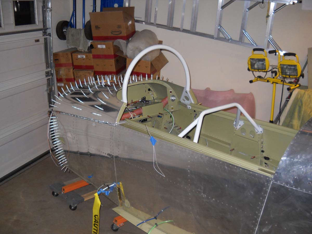
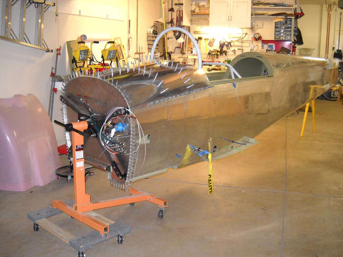
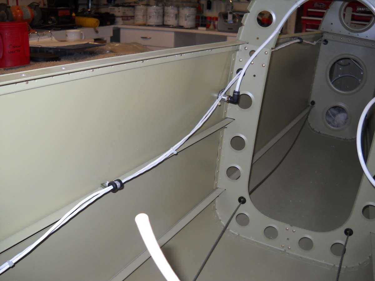
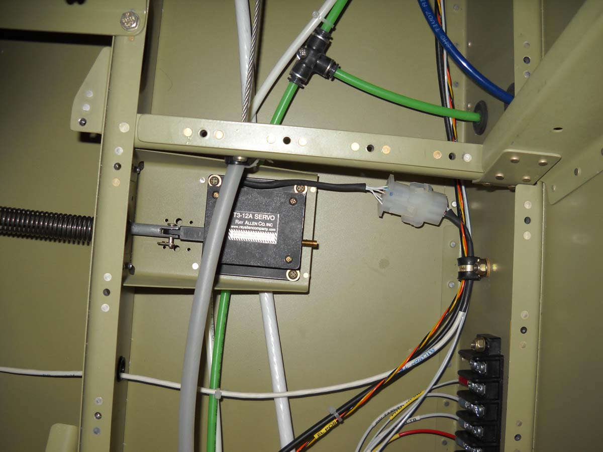
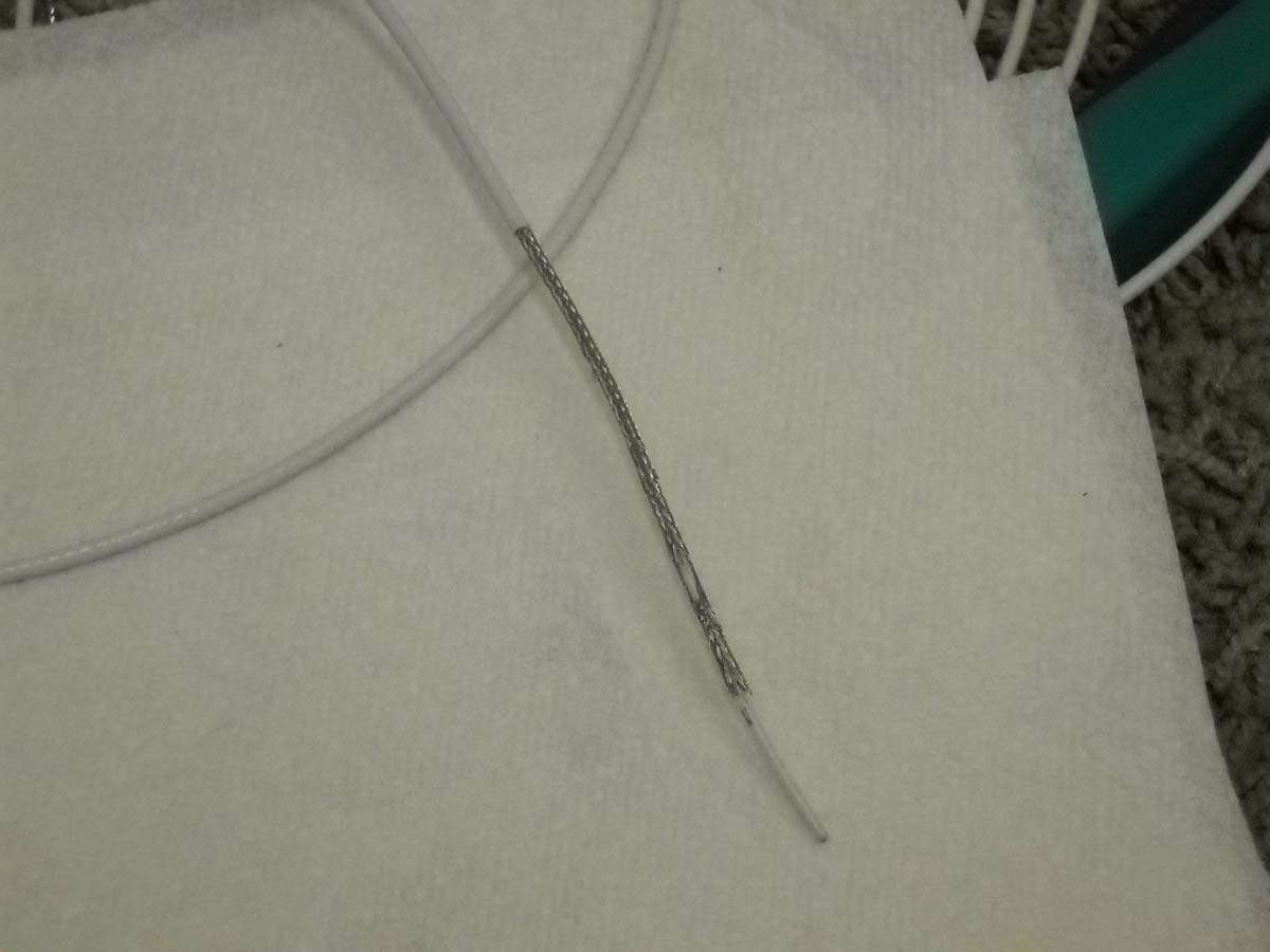
I am no longer a wire virgin. I ran some wire to the tail. Here is the shielded three conductor wire for the tail position light/tail strobe (probably to be AeroLed) and the five conductor elevator trim servo wires. I pondered how to do this for some time then decided to just start something and do it. Done. As can be seen, I am trying to get everything in the aft fuselage done before riveting the top skin on.
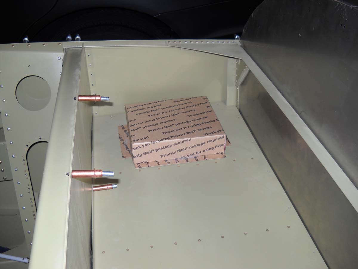
As part of the planning process, I have considered using the VP-X Sport as the basis for my electrical system. Several advantages, not the least of which is simplicity and multi-tasking and the interface with the Dynon Skyview. A bit pricy, though, and some flexibility is lost. The decision is not yet made, but as part of the process I wanted to see where I could install the unit. I constructed a mock-up from high quality cardboard (don't look too closely...the post office might be upset) and tried different places. Does not seem to fit anywhere very easily, but this seems to be a good spot to me. I would lose some of the baggage area but it would be simple and clean to mount it here. Would add a cover for protection. Easy access to the back of the panel for wiring bundles.
Truth be told, after considering this for a couple of weeks, I am back in the 'build it myself' camp using, primarily, fuse blocks in lieu of breakers. We shall see.
September 6, 2012
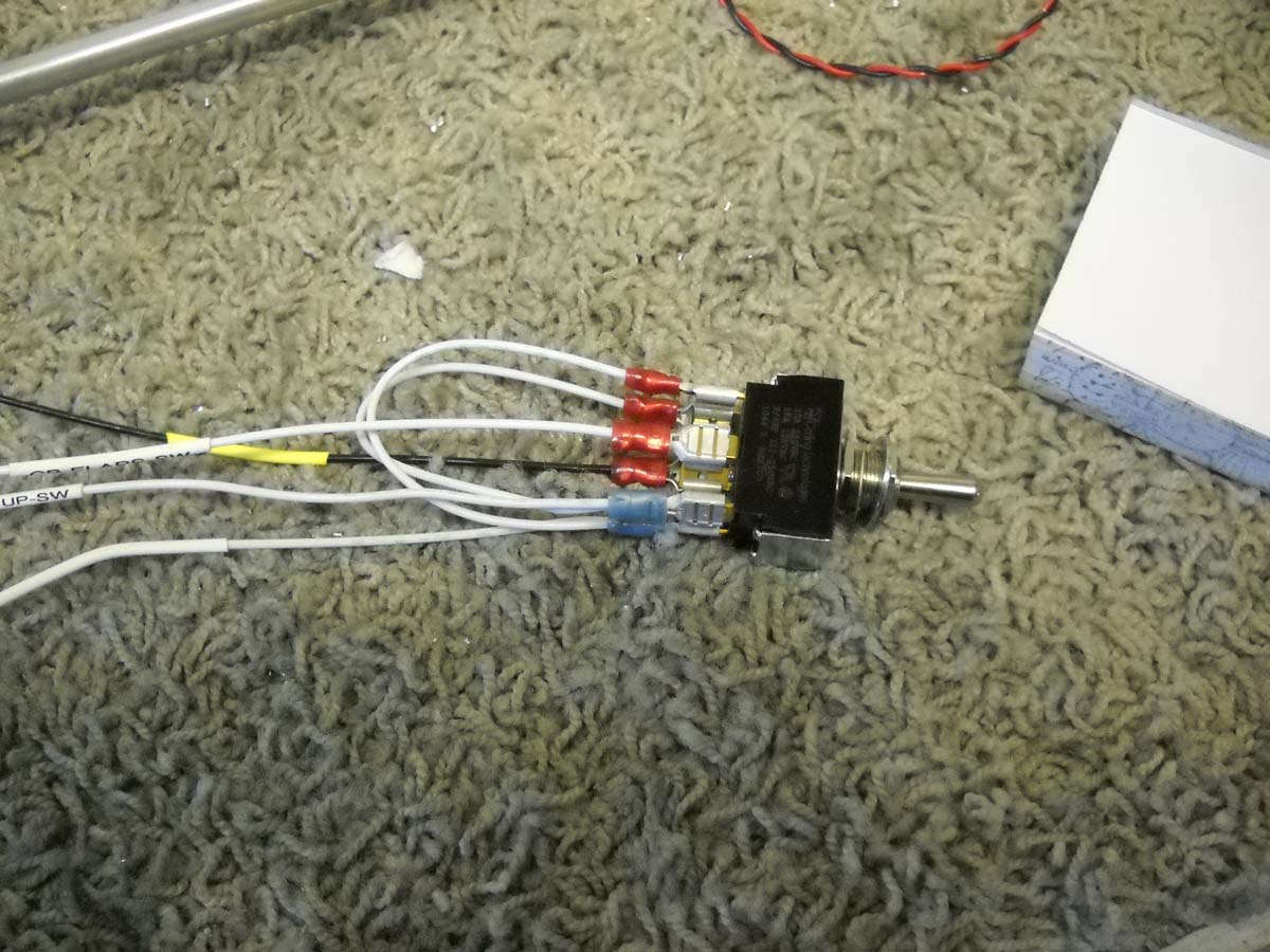
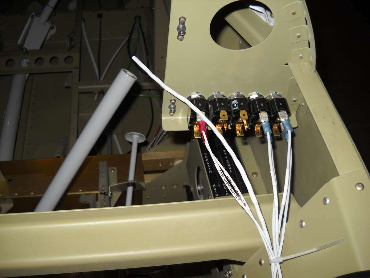
Here is the flap switch, a three position switch spring loaded to the up and down position. This should work for my purposes; not too fancy but quite manageable. No preset positions; I will look and feel the flaps well enough to know where they are. My primary position indicator will be glance outside at the flaps but might also add a simple panel indication also.
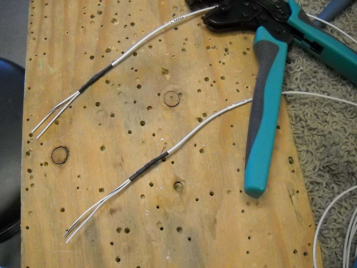
The wiring is straight out of the Bob Nuckolls' AeroElectric book, an invaluable resource for me at this point. Crimped and ready to be installed.
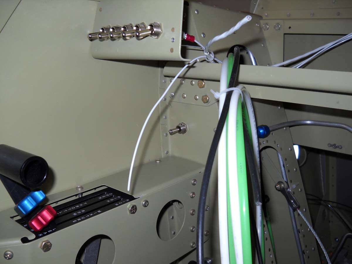
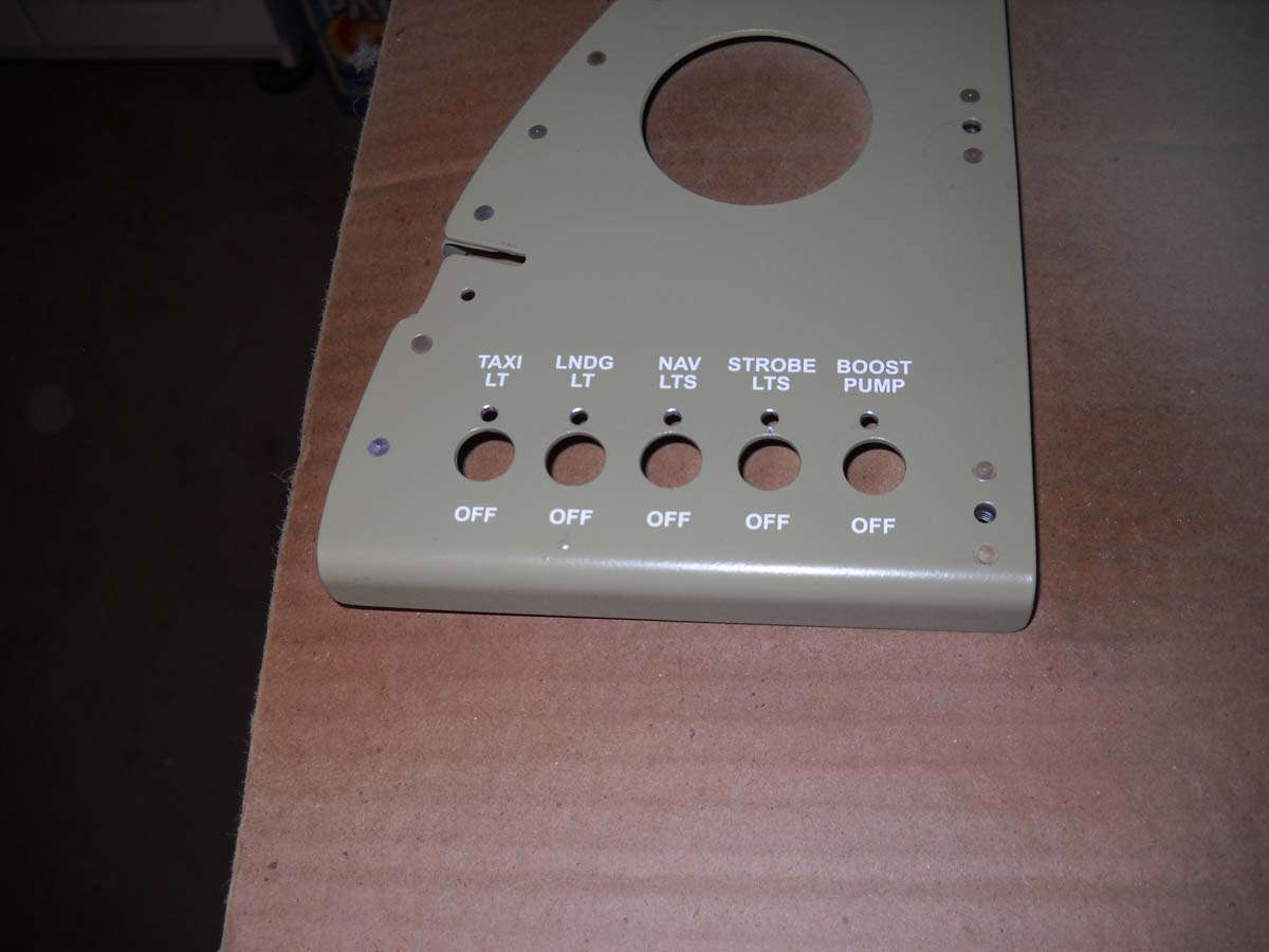
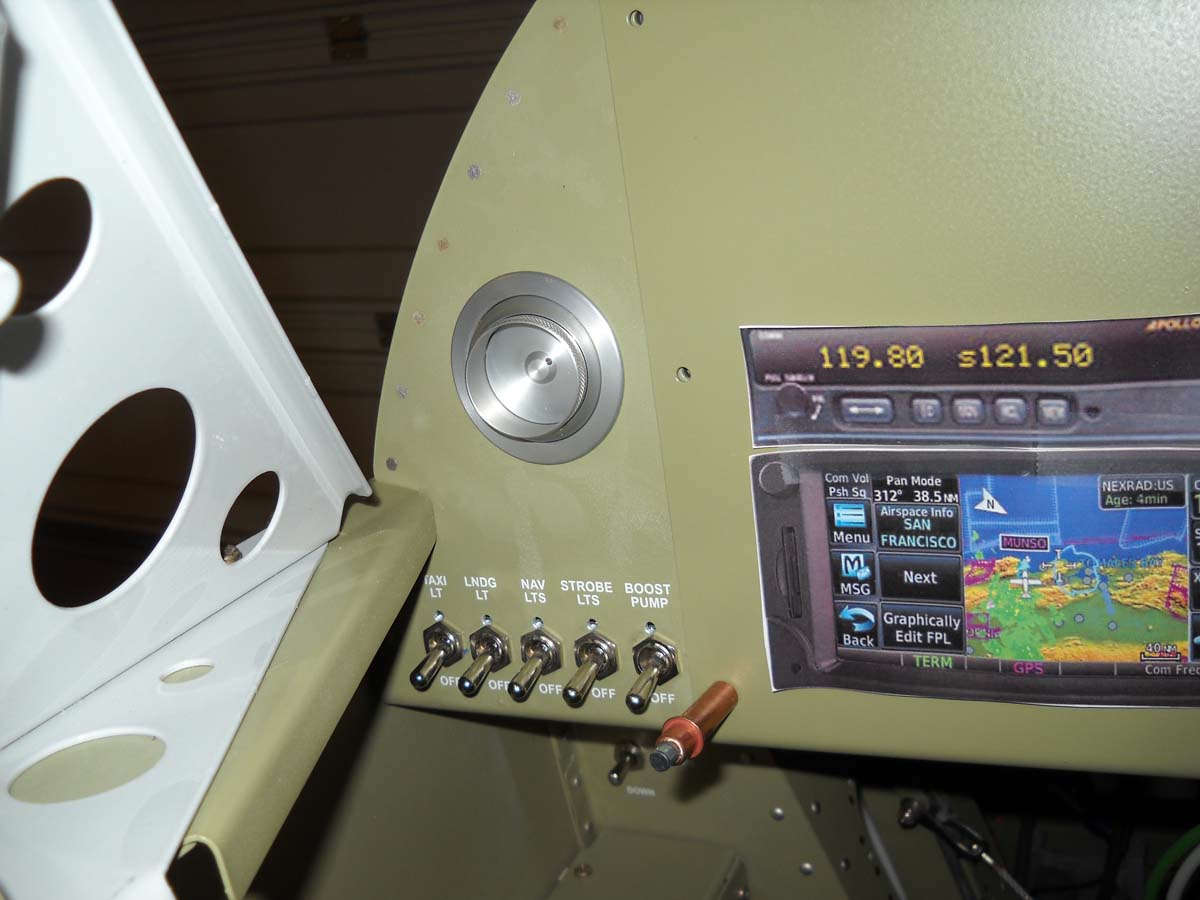
Here is the flap switch mounted forward of the throttle. Should be convenient and easy to manipulate in conjunction with power adjustments. Above the flap switch are five toggles for, from left to right, the taxi light, the landing light, the nav lights, the strobes, and the fuel boost pump.
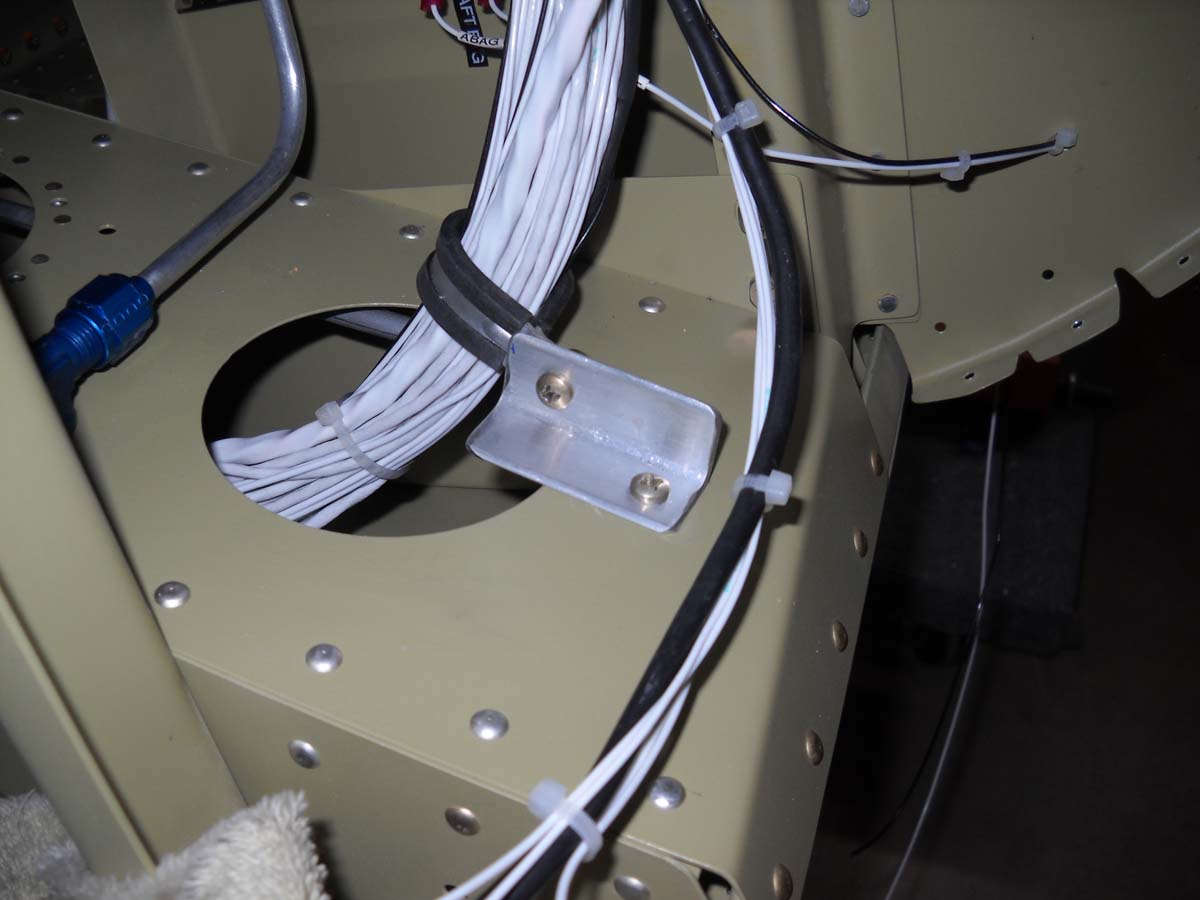
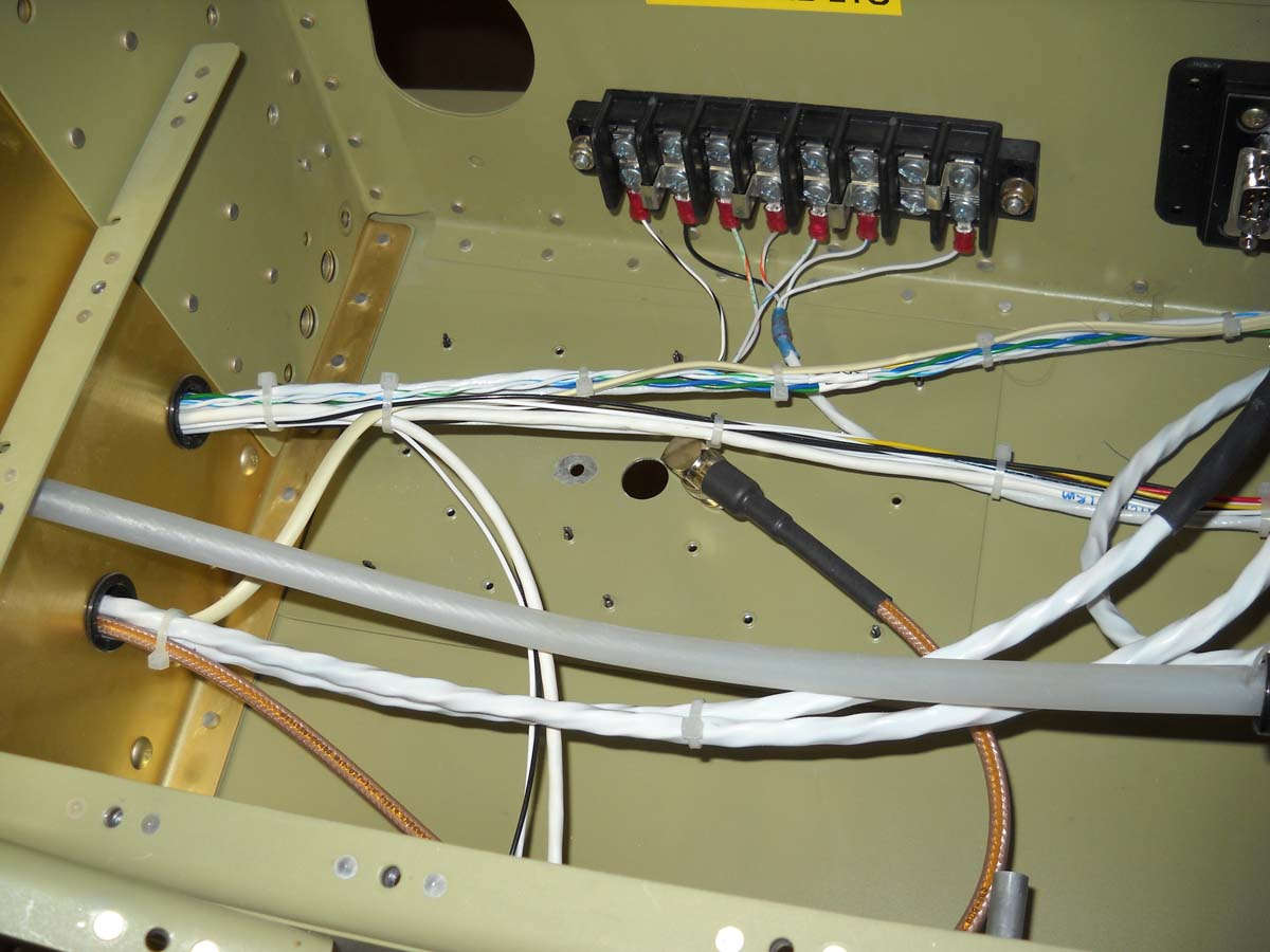
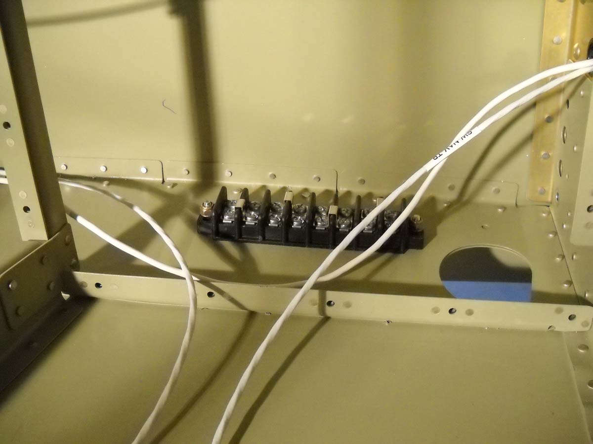
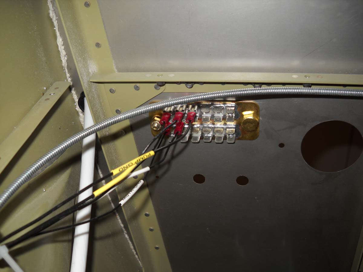
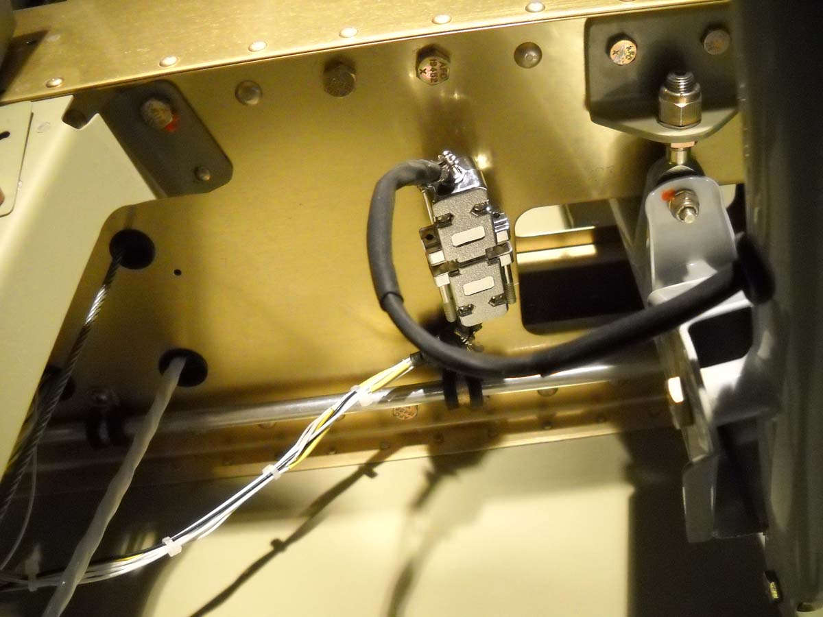
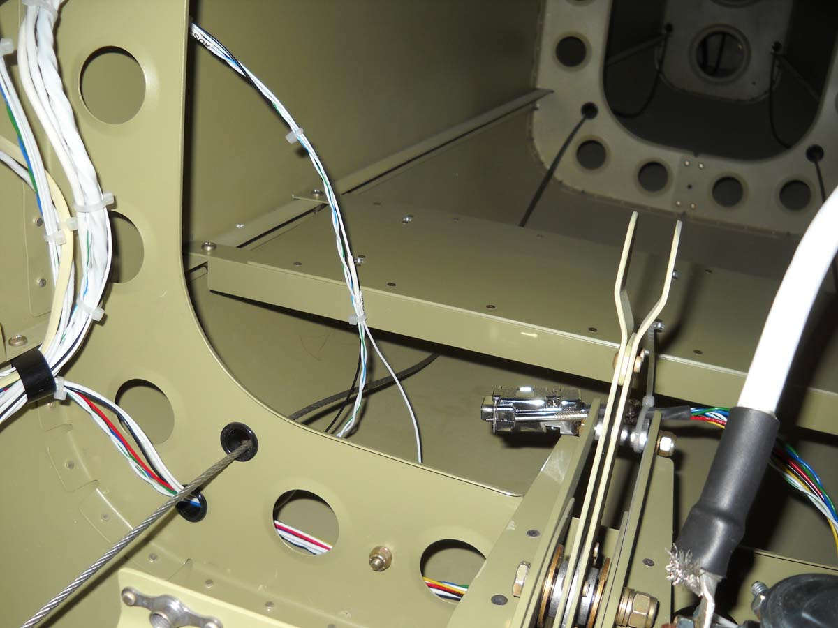
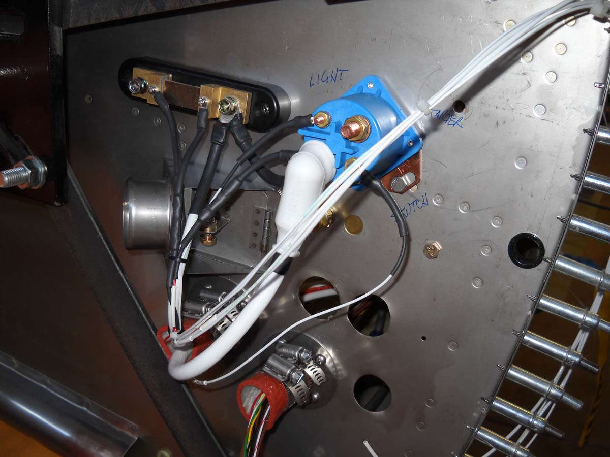
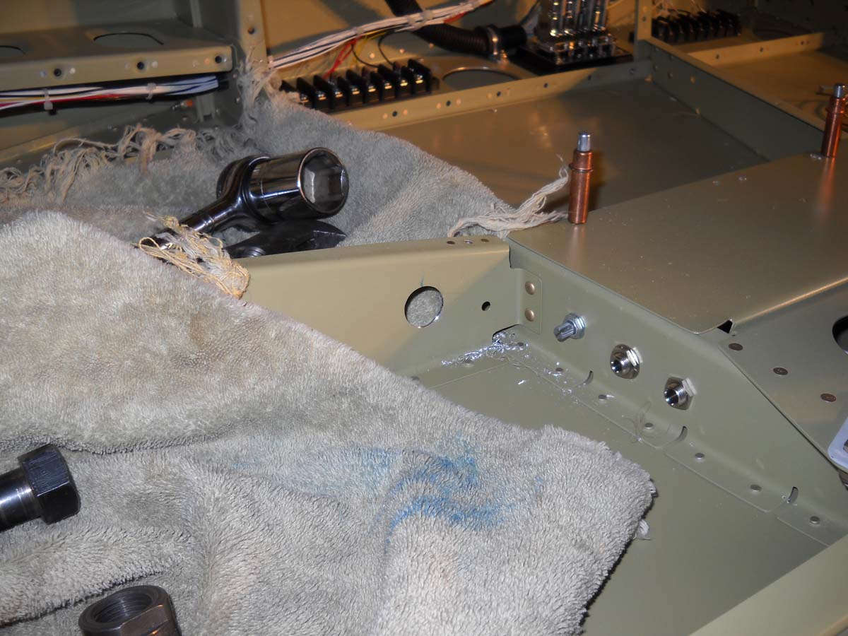
I thought about how I was going to run the wiring for the AeroLED lights I am planning to use. They use three strand shielded cable, with the provision that the shielding is grounded along the entire length of the wiring. Thus, where they connect together (switch wire to the wires going to each wing and tail for both the navigation lights and strobe lights) I needed to plan it a bit. I purchased this terminal strip from B&C: it has sixteen connections for where I need fifteen, so it will work just fine. I added four jumpers with the net result is that this will handle the connections of four circuits.
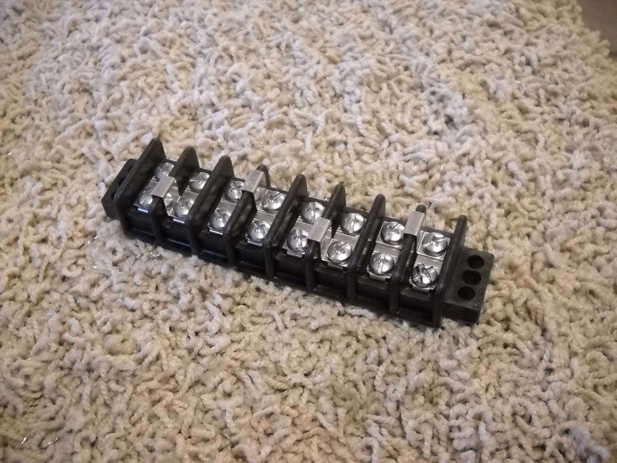
I mounted it on the right side of the fuselage below the floor on the wall just aft of where the aileron control tube passes out of the fuselage. The three sets of wires will connect here, along with the shield grounds. The shield grounds are attached using solder sleeves and then joined at the terminal blocks. More to come on this.
November 4, 2012
Not a lot of visible progress over the past two weeks. I have not been able to spend too much time working directly on the RV-8, but did a bunch of conceptual planning on the electrical system. I blocked out an list of switches and circuit breakers I needed and went ahead and placed an order. When it arrives, I will have most of what I need less some wire stock and some odd components that I will think some more about.
I also modified the battery box to accept the Odyssey PC680 I expect to eventually use. The battery is 3" wide so the standard box needs to be modified in some manner to accept the narrower profile. Two pieces of angle will work fine. I drilled and added nut plates to secure them to the box, with cutouts added to allow the standard screws to be used that secure the box to the airframe. A bit of primer and this will be ready to be mounted into place.
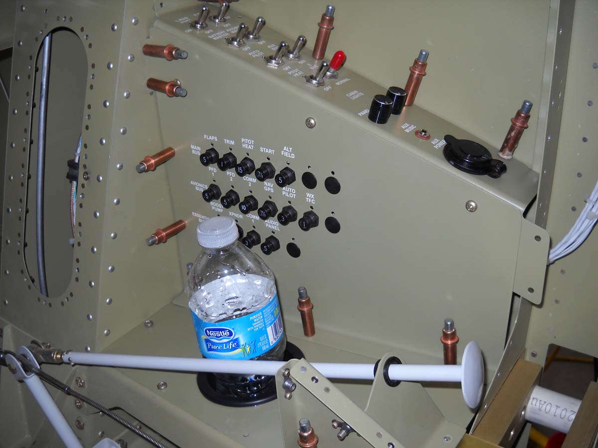
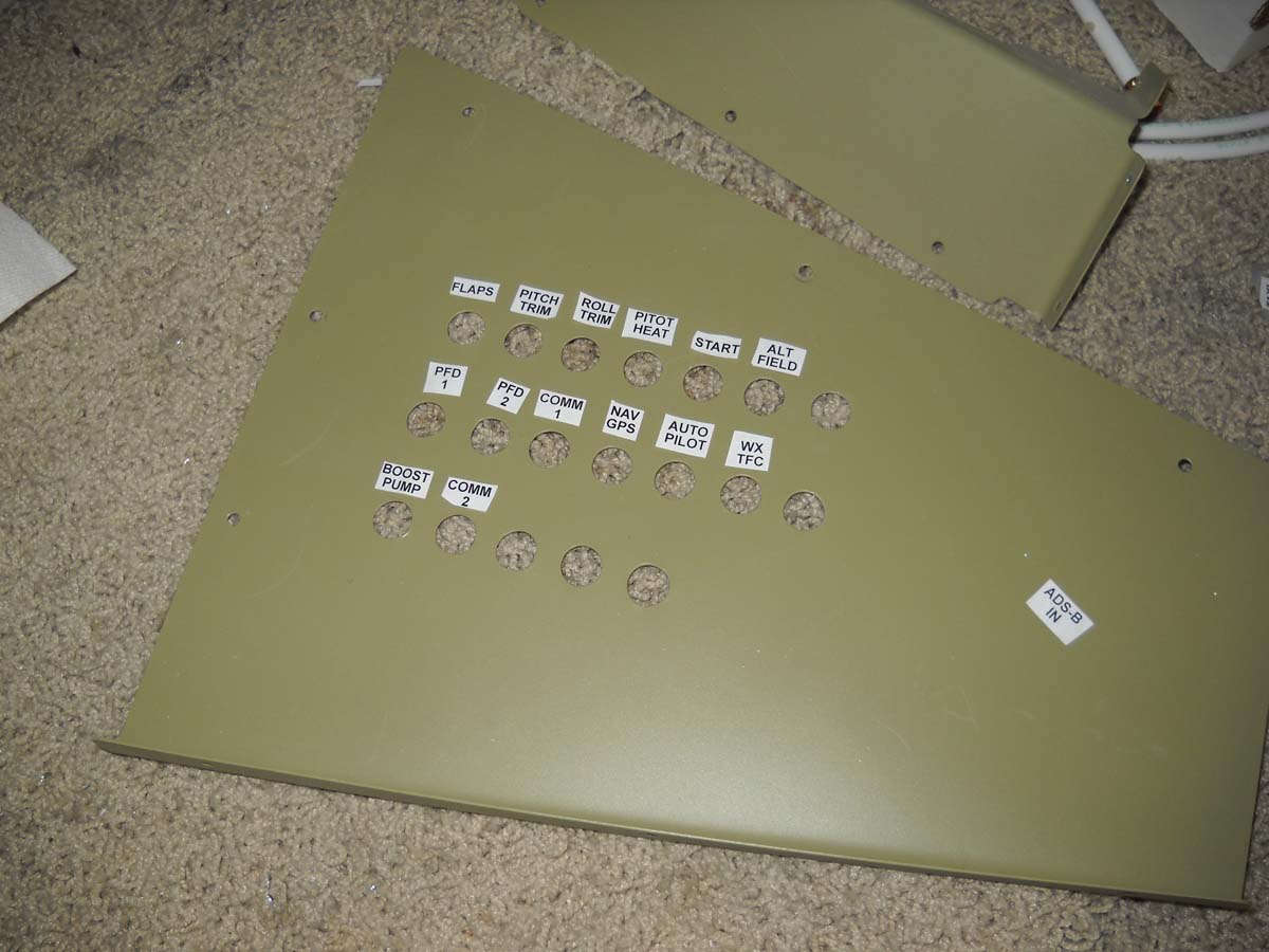
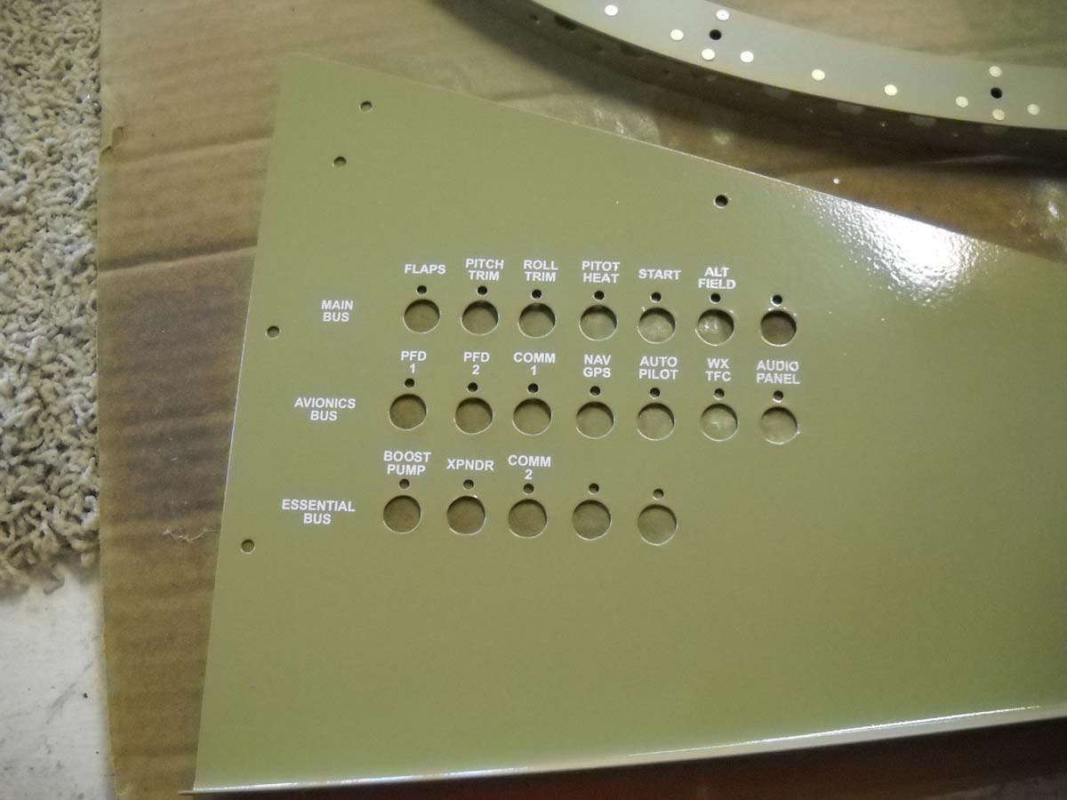
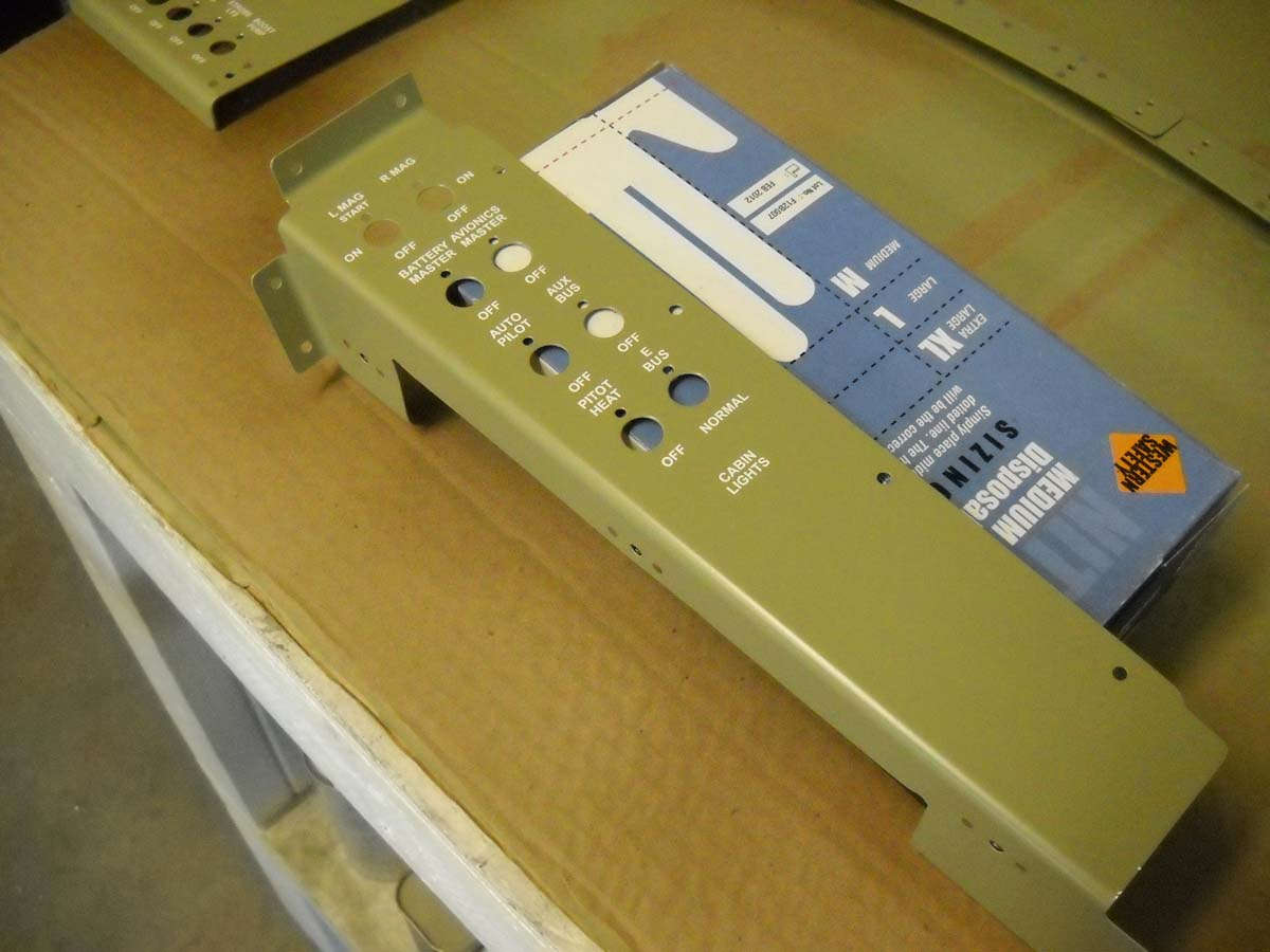
As part of the process, I've been playing around with panel markings. I think I will use the dry transfer method to apply the markings. I want a fairly simple panel as far as markings go; nothing too fancy is required here so basically each switch will be labeled and that's about it. Also, the circuit breakers will need to be labeled. Here is the circuit breaker panel with mockups of the labels that I am checking for fit.
I also crimped terminal ends on one end of my 2 AWG battery cable and ran it from where the battery box will go (aft) all the way through the firewall. I will pay more attention to the wiring in the weeks ahead and expect to make good progress.
November 19, 2012
Continued work on the electrical system over the past several weeks. Worked here and there around other demands, projects, and work schedule. I did make some progress, though.
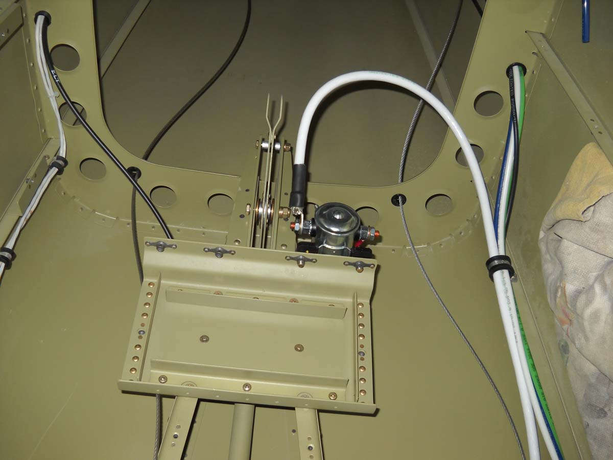
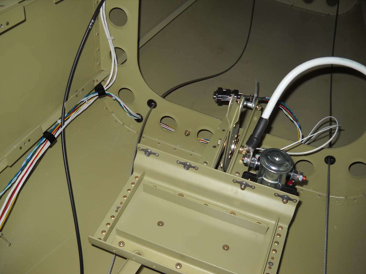
I completed the modified battery box to accept a smaller Odyssey type battery by adding some angle aluminum that screw attaches to the box. Once completed, I attached the starter contactor to the battery box.
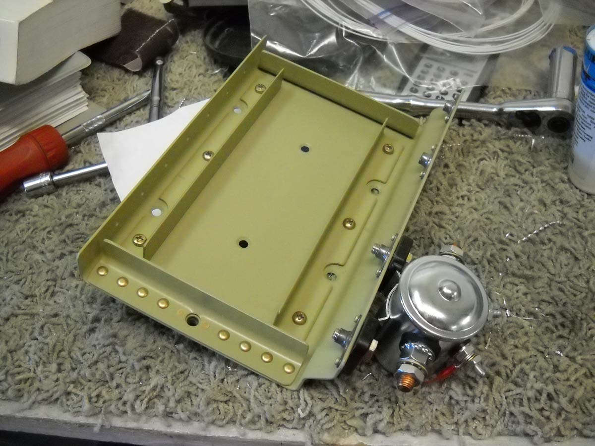
I then attached, permanently I hope, the battery box into the rear fuselage. I then attached the 2 AWG cable that runs from the battery contactor to the starter contactor that will eventually be mounted on the firewall. We will see later if this cable alignment will work with the autopilot pitch servo that attaches to the bellcrank seen to the rear of the battery box.
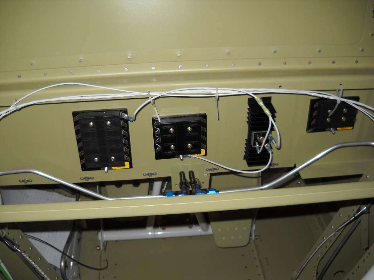
I permanently installed the main fuse bus, the essential fuse bus, the diode that can isolate the essential fuse bus, and the hot battery bus. They are installed on the lower part of the aft forward baggage compartment bulkhead. The four can be seen in order here from left to right. Some wires are seen going in here also.
I had ordered my dry transfer sheet from Camera Graphics in Portland, Oregon, and it arrived a few days after I placed the order. I had boiled my needs down to one 8.5" x 11" sheet, and still had duplicates. My needs are simple; this will not be an overly complicated or busy panel.
The process of applying the transfers is very straightforward and simple. After the transfers were completed, I applied about four coats of a matte clear coat to protect the transfers. Turned out quite well in my humble opinion. There are some flaws, but it will be quite functional, thank you.
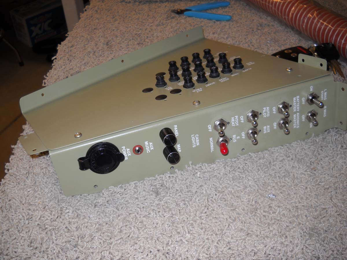
Here is the circuit breaker panel.
And the switch panel. There are eight switches here now plus there will be at least one cockpit lighting control here.
And the lower panel switches that lie above the throttle.
Next, these panels will have the switches installed and wired, and the integrated into the wiring I have already done. It is good to be installing things permanently into the fuselage.
November 29, 2012
More electrical work these past ten days. Mostly short sessions but that is better than not working on it at all. To date, I'm happy with how the wiring is coming together.
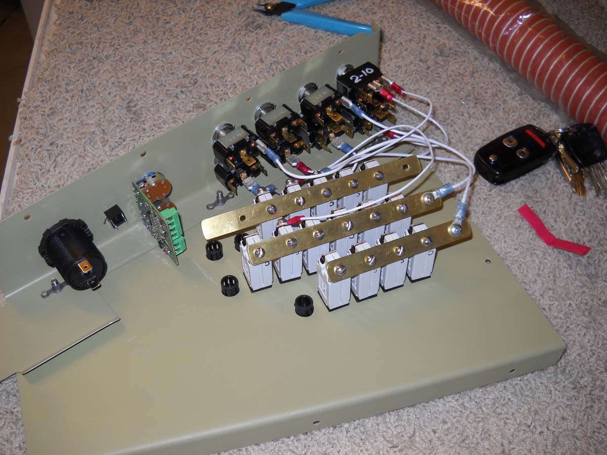
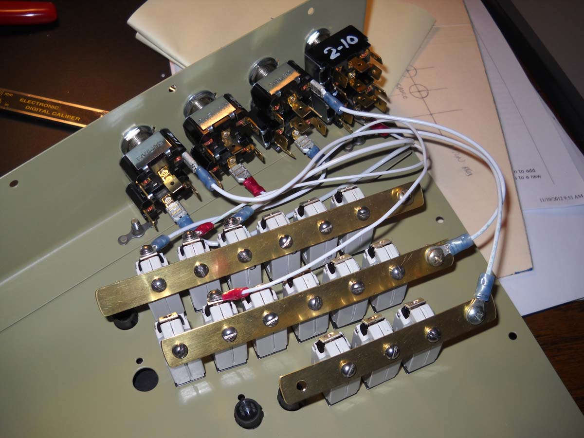
I completed the switch installation and circuit breaker bus assembly for the main switch panel. Here is the back of the assembly with the three buses containing a total of fifteen breakers. From the top is the main bus, the avionics bus, and the essential bus. The open breaker hole on the avionics bus will get the audio panel circuit breaker, but I decided that this should be on the essential bus, so it will have a jumper wire to the lower bus and not join its brethren on the avionics bus. Not as elegant as it could be; I could redo the markings on the panel and add the breaker to the bottom bus instead, but I'm not going to do that.
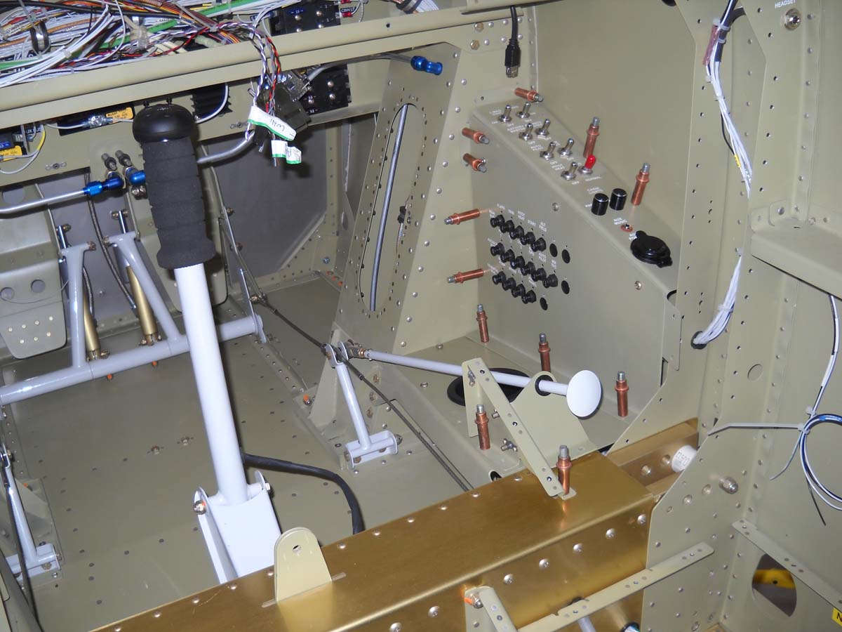
And the outside of the switch panel in place on the right side of the cockpit. On the aft side of the switch panel will go the cockpit lighting controls. I have not yet worked all those details out, nor have I purchased the materials; thus, the lack of switches there.
This is the back of the smaller switch panel located just above the throttle. All the wires are attached here except those for the nav and strobe lights. A bit more complicated to do those two with the shielded wires, but will do it shortly.
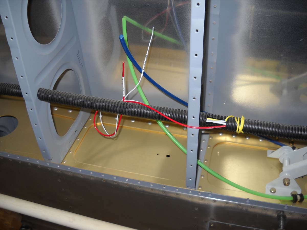
This view shows the left wing mid wing area with the conduit and the wiring for the pitot heat controller. I am completing the wing wiring so I can do the wing lower skins. The power (red) and ground (missing) wires are 14 AWG while the smaller white wire is for the pitot heat light and will be wired into the Dynon Skyview EMS module for display later. Plan ahead, etc. The blue tube is for the Dynon angle of attack display, plumbed from the pitot tube. The green line is the hookup to the pitot tube for airspeed display. Both tubes will go to the Dynon ADAHRS unit, with the pitot split off for a raw data airspeed indicator in the cockpit.
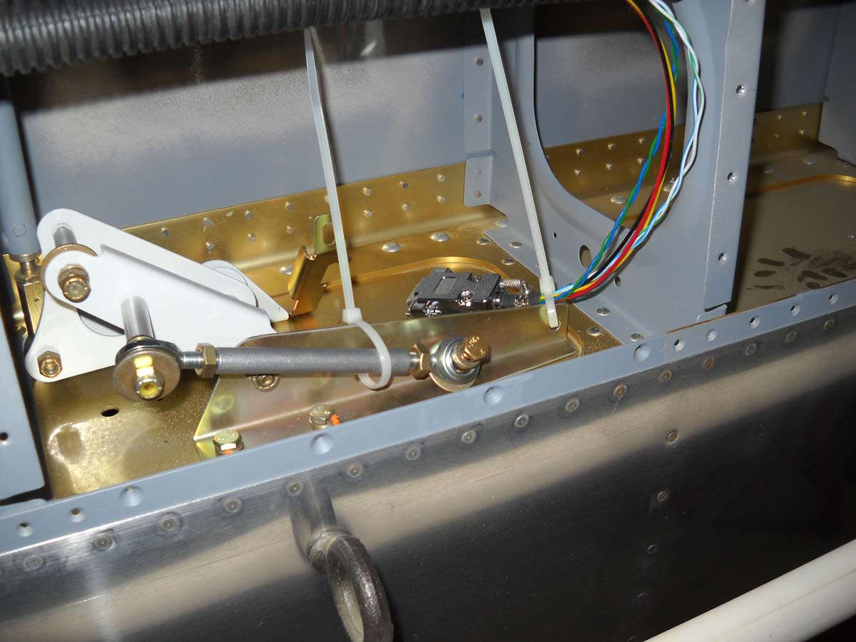
In the right mid wing area is the aileron bellcrank seen here with the Dynon autopilot roll servo mount replacing the standard bellcrank mount. Also seen here is the push rod that goes from the bellcrank to the servo, and the wiring cable and 9 pin connector that will connect to the servo electrical leads. Plan ahead, etc.
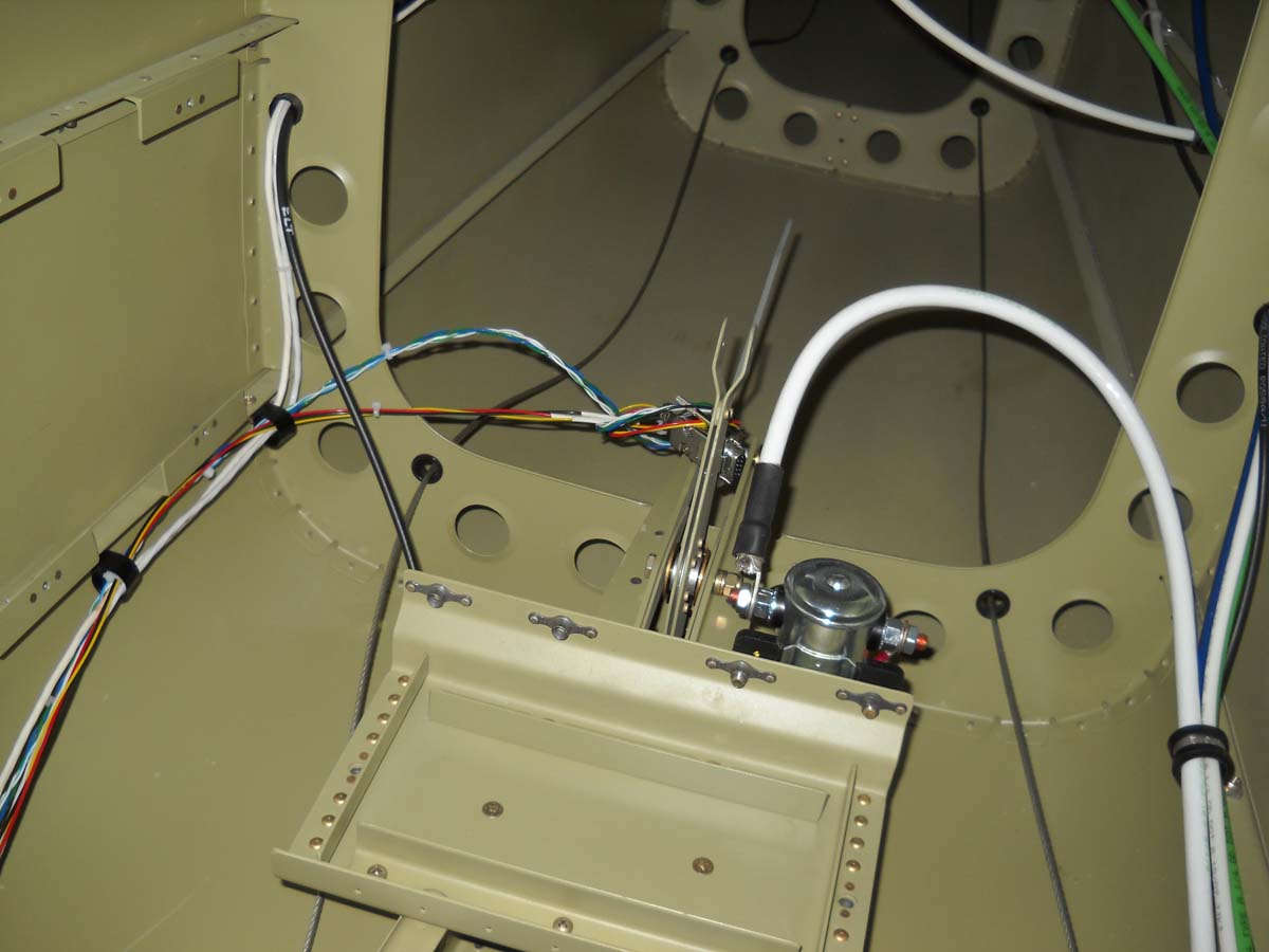
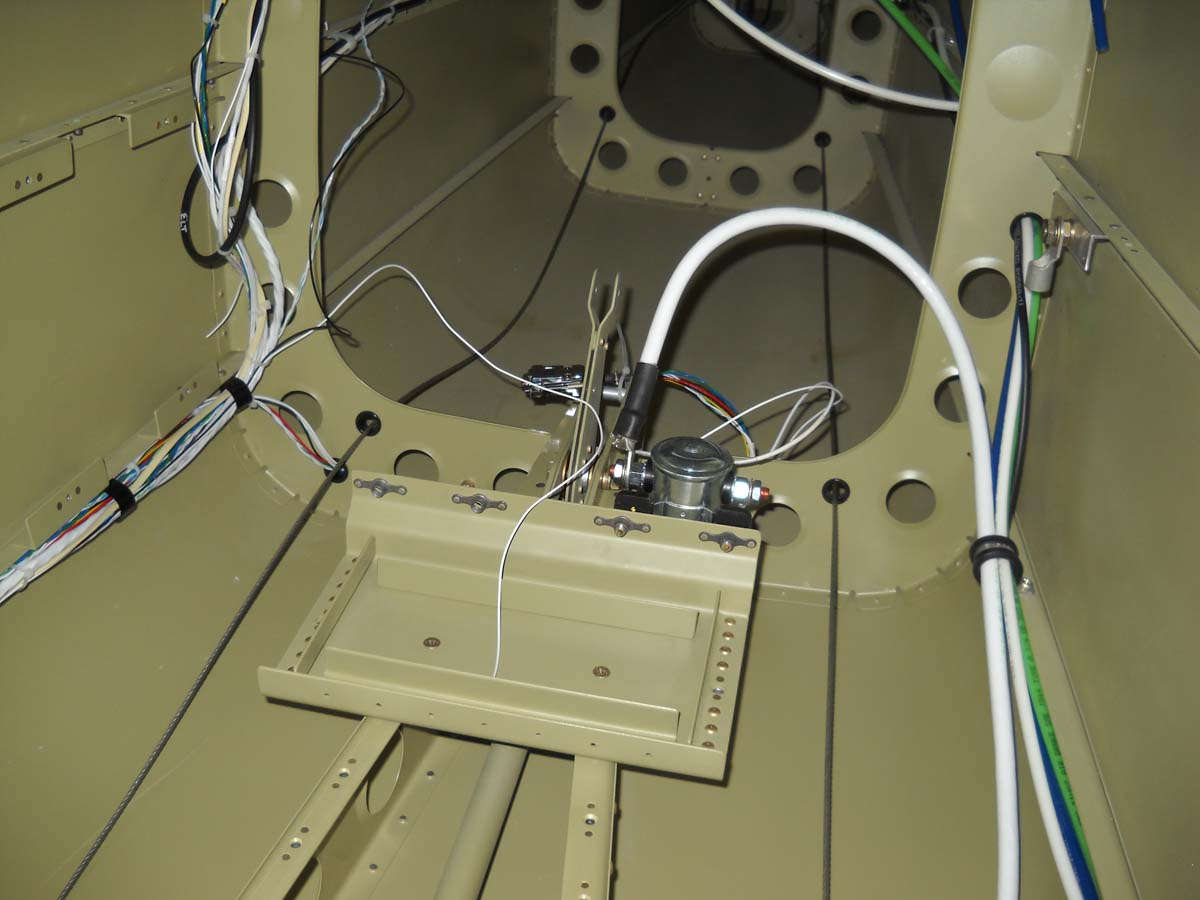
Here is the wiring that will go to the pitch servo mounted aft of the battery box and connected to the elevator bellcrank. This is also a nine pin connector but only two pairs of serial wires and one power, one ground, and one autopilot disconnect are wired to the servo itself.
And that's were I am right now.
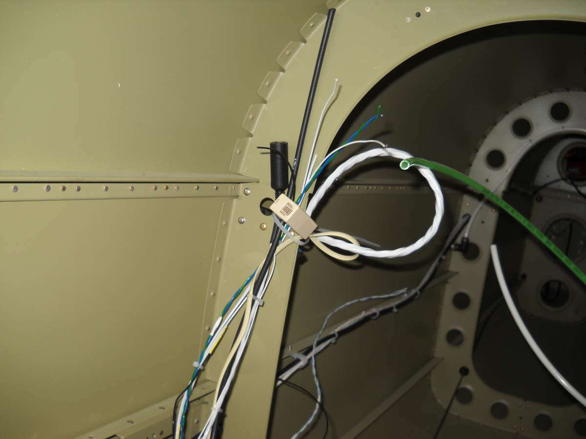
January 20, 2013 Part of the electrical installation is this 24 tab grounding point from B&C that is mounted on the aft side of the firewall on the left side (looking forward). Most of the electrical grounds will be routed right to this point.
I spent some time working on the routing of the wiring harness that will be attached to the elevator autopilot servo. It needs to be kept clear of the elevator push rod (not installed in this view) and running it behind the bulkhead and under the pushrod and then back to where the servo is mounted seemed to be the best way. Which is what I did.
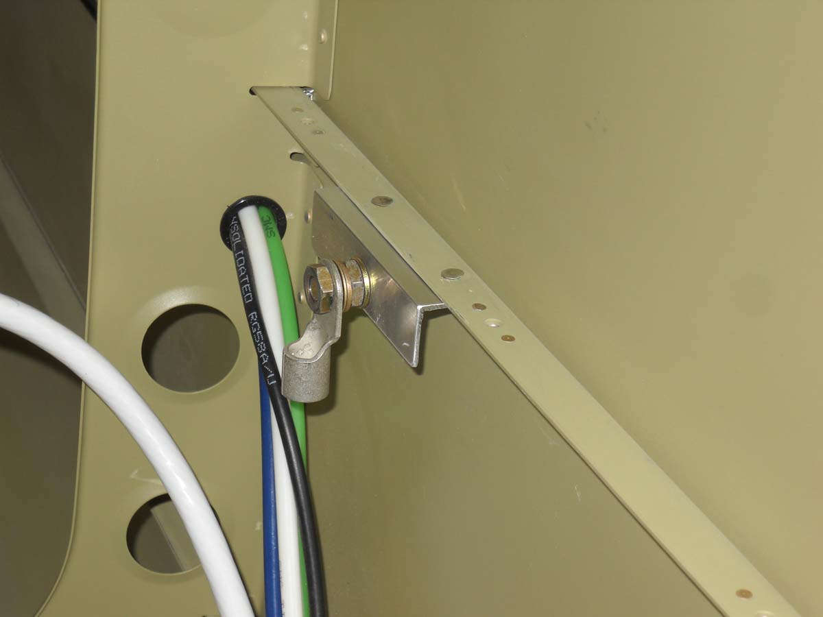
And, here will be the grounding tab for the battery some day. Basically, I riveted a piece of angle to the longeron (after the paint was scuffed off). This is located adjacent to the battery tray on the left side of the fuselage.
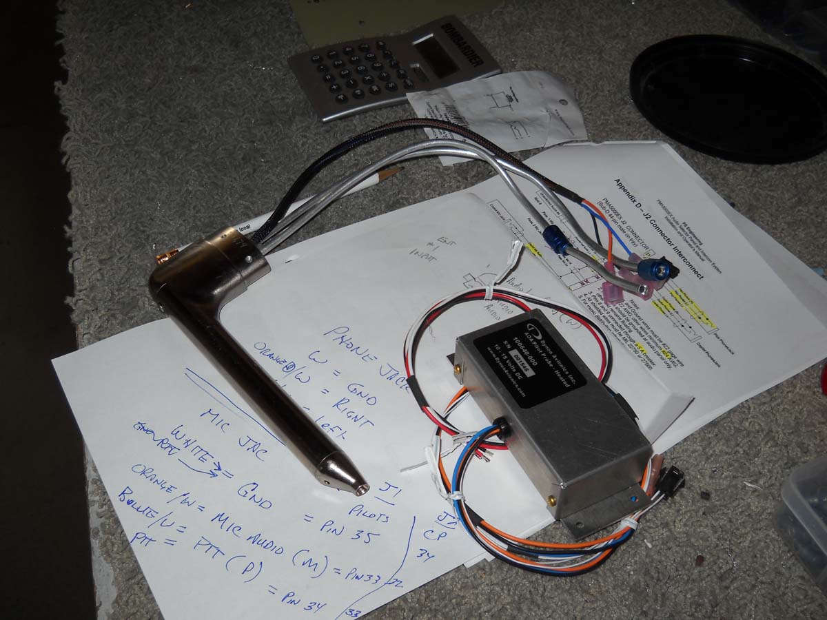
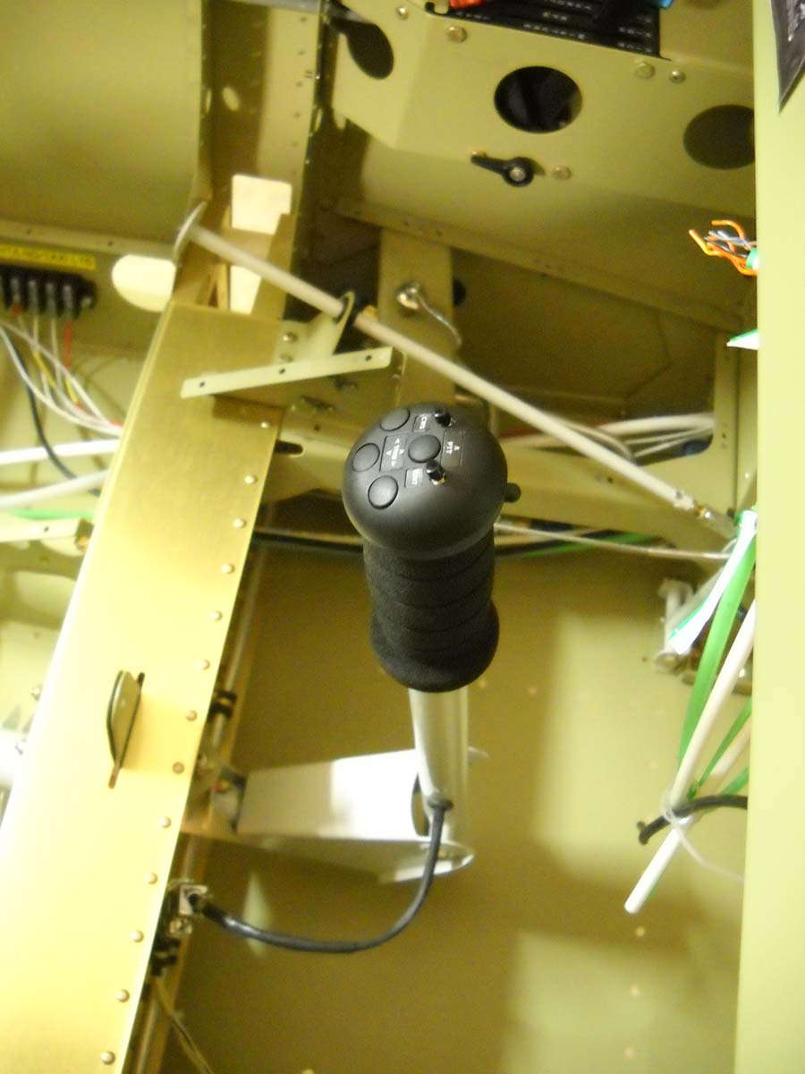
I spent quite a bit of time researching how to have the stick grip wires exit the front stick and, after due consideration, came up with this: a 3/8 inch hole drilled on the right side of the stick near the bottom, with a 9/32 rubber grommet (from Home Depot) inserted for edge protection. This size worked perfectly for the nine wires that come from the stick grip. This view was taken with the fuselage rotated on its left side.
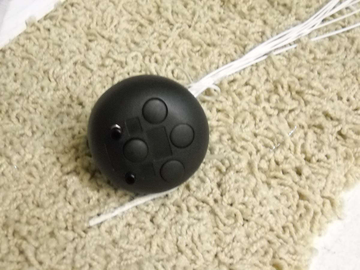
And, here is the stick grip with the wires soldered into the gip, courtesy of someone who knows well how to solder (thanks Duc!) There is no way I could get all those little wires soldered to all those tiny terminals without ending up with a massive globule of solder all over everything.
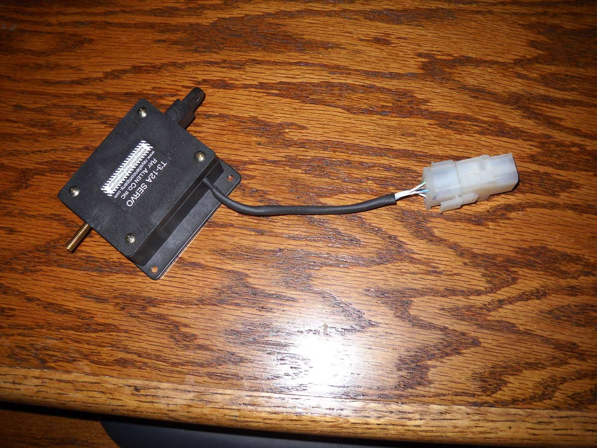
And, here is the aileron trim servo with a AMP connector added. It is ready for installation and final wiring at this point.
Okay, all caught up now to where I was in early January. I've done quite a bit of work since then which I will add here shortly.
February 3, 2013
Back at it, or rather pushing along a bit at a time. Continuing working on the electrical system, planning and installing wiring runs and figuring out where some of the black boxes will go.
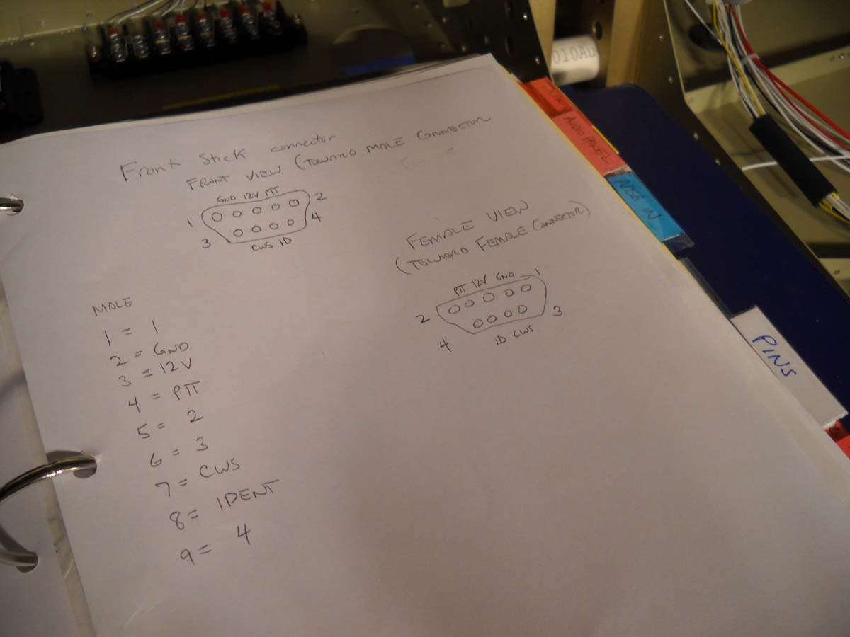
I completed the wiring for the front stick, that bundle consisting of nine wires that control the trim, the push to talk button, a control wheel steering button for the autopilot, and an ident function for the transponder. I used a d-sub connector to join it to the wiring already installed in the control stick. Here I am checking the continuity of the wires and trying to establish the correct hookup for the elevator trim.
Keeping careful notes on the pin positions for the control stick connections. I hope to redo these, time permitting, but these notes will work for now.
Here is the control stick connector finished and hooked up.
And a view of the front control stick essentially complete and ready for action...in a few years.
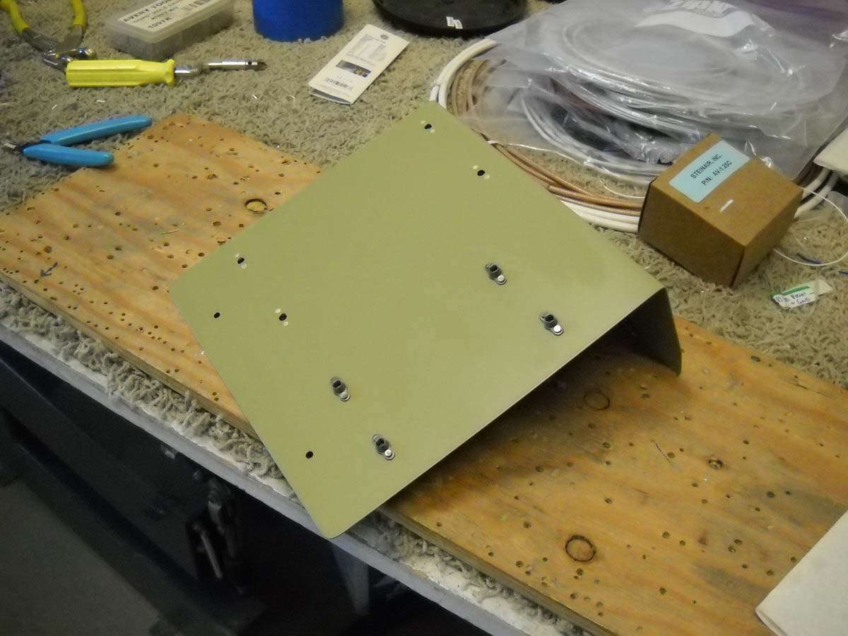
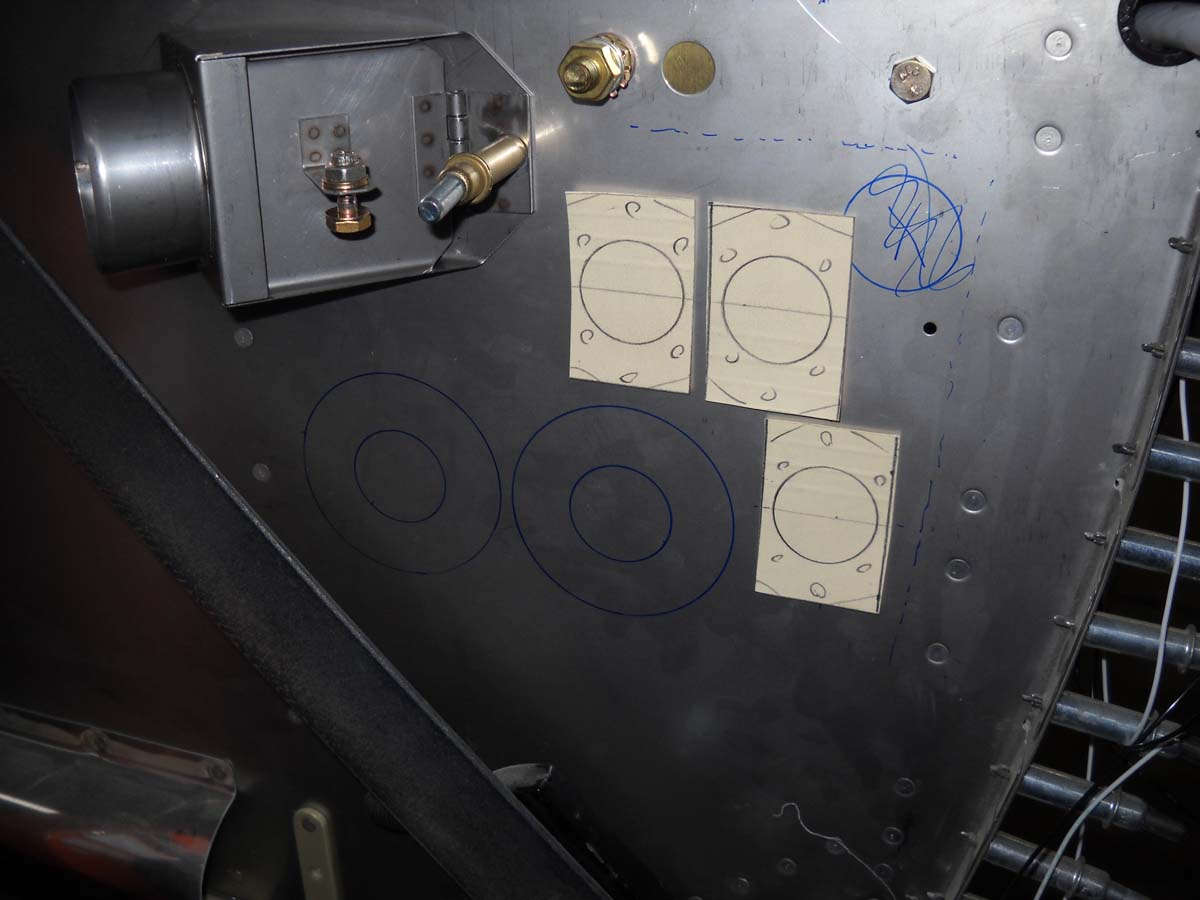
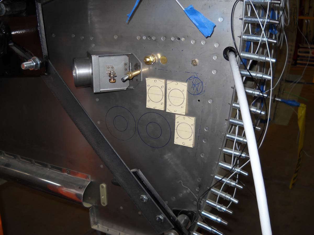
In the process of laying out where the "black boxes" are going to go. I am installing the Skyview system and made some paper cutouts of the Engine Monitoring System (EMS) box that has three wiring harnesses attached, and the ARINC-429 box, with two harnesses. The EMS obviously monitors the engine sensors and feeds that data to Skyview system via the network setup. The ARINC-429 box allows an interface with, for me, I hope, at Garmin GTN-650 WAAS/VHF receiver. There is not a whole bunch of room between the instrument panel and the aft bulkhead of the baggage compartment. What I think will work is a shelf installed on the two supports toward the right side of the fuselage, with the EMS installed right side up on the top and the ARINC-429 box installed inverted beneath it. I bent up a shelf that I think will work and test fit the size with the paper cut outs of the boxes fitting. I think there will also be room for the Skyview backup battery and the ACK E-04 ELT audio monitor also. Here is the tentative layout, but I have since cut the width of the shelf down to eight inches vs. the twelve I started with.
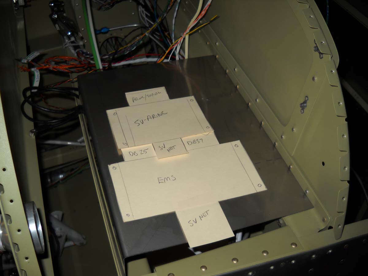
Another view from the other side. The ten inch Skyview main display needs about three inches of clearance behind it, so this will work okay for that. On the left side of the panel, the GTN-650 installation requires the full twelve inches available.
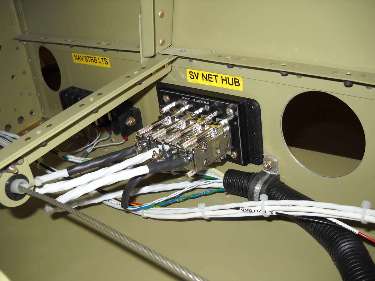
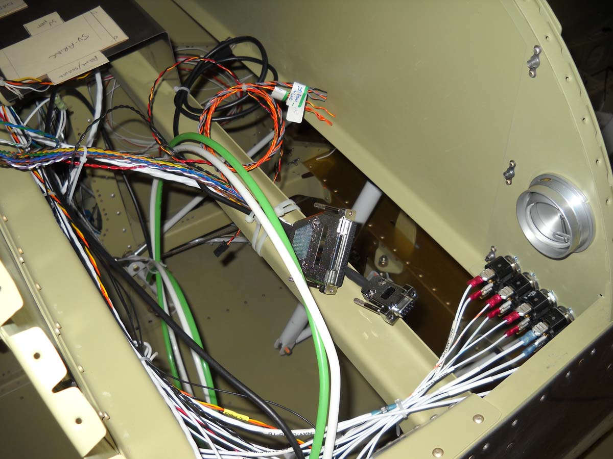
Here is where the SV-NET-Hub is installed on the right side of the fuselage beneath the pilot's seat area. Here four of the five ports are connected (ADAHRS, autopilot pitch servo, ARINC-429, and connection to the Skyview network itself. The last port will be used to attach the autopilot roll servo coming in from the right wing.
I pretty much finished the wiring in the aft end of the fuselage. Key to this was obtaining a ACK E-04 406 mhz ELT connector from the ACK folks....thanks to them but, then again, now I am committed, happily, to that ELT which I think is the best available in the price range.
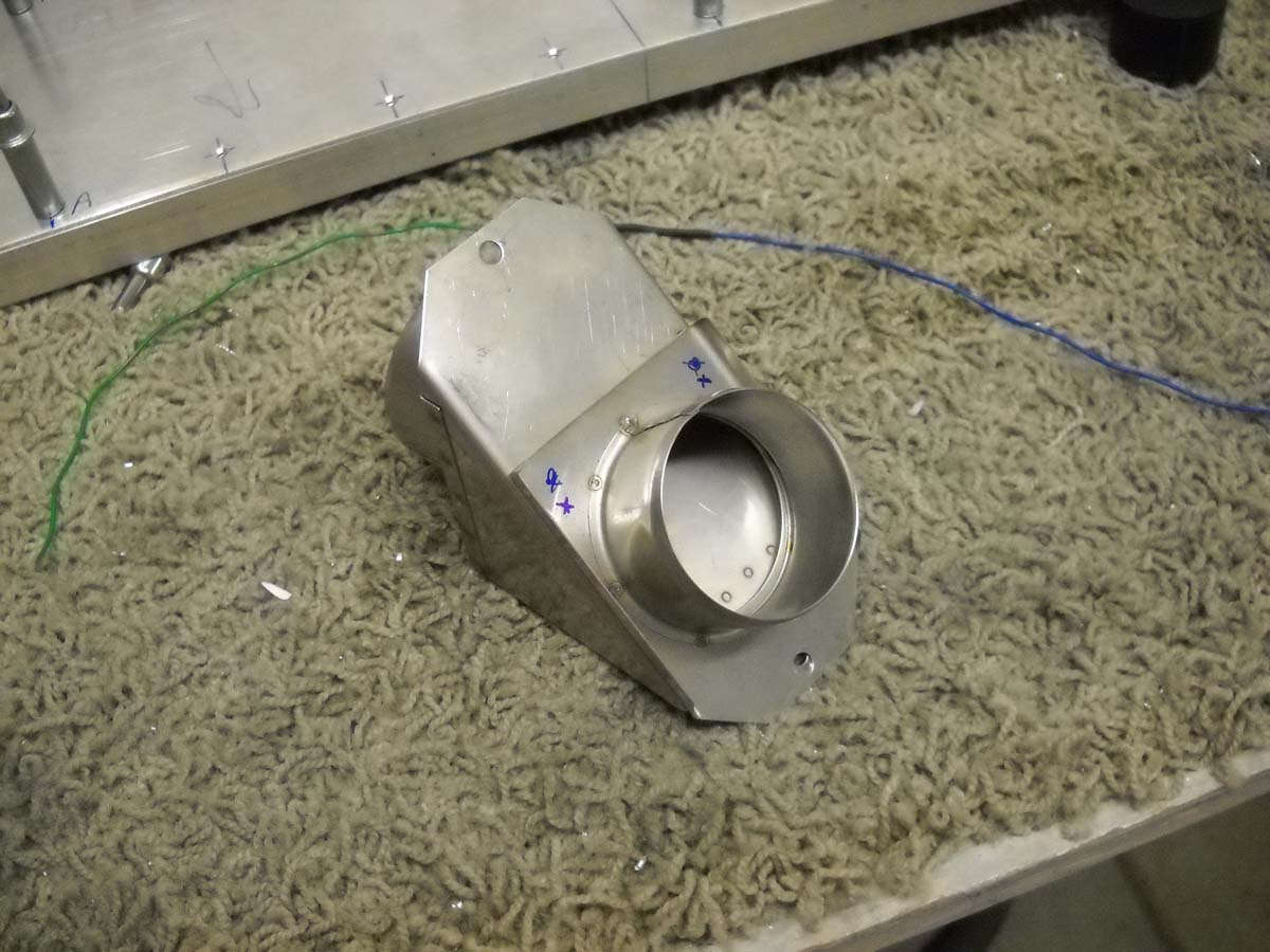
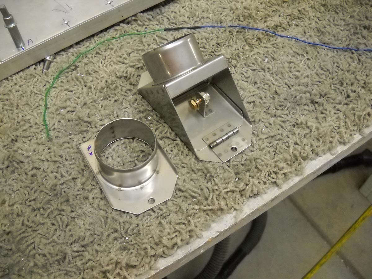
Having read numerous accounts of the less than stellar performance of the standard Van's air vents, I am replacing the plastic, poorly sealing vents with some very nice metal ones from Stein Air. Pricey but high quality. This necessitated me fabricating a replacement mount for the vent installed next to the aft stick for the rear passenger. This vent brings air in from a NACA vent in the right wing and is just ambient air...not heated.
Here is the vent roughed into where it will be installed.
I purchased the Skyview main display harness and it is installed along with one of the network cables. The harness is prewired and awaits me to make each of the connections. I have spent quite a bit of time figuring out a "pin map", as it were, to get ahead of this process a bit in the planning.
Back to the aft end, here is the ELT and Skyview XPNDR wiring ready to go and zip tied out of the way. The phone line connection is for the remote monitoring panel to be mounted on the instrument panel. The black connector is the one provided by ACK and required some tedious soldering of connections (thanks again, Duk!).
You can't see it too well here but the ELT and the Dynon XPNDR-262 units will mount vertically on a panel adjacent to the battery. When I had laid all this out I was not aware of the Dynon ADS-B box they had under development. That ADS-B box will allow direct reception of ADS-B traffic from those using the general aviation UAT transponders, and also the FAA weather feed from the ADS-B system. Combined with the Dynon XPNDR-262 ADS-B compliant transponder and the GTN-650 GPS position feed that goes into it, this should be a fully compliant ADS-B system that will interact with ATC and/or all other ADS-B and/or radar transponder equipped aircraft in the vicinity of this RV-8 when it is all hooked up and operating.
That is all to say that I don't have room for this added ADS-B box on the same panel as the ELT and transponder, and after talking to Dynon, they don't think it should be mounted adjacent to the ADAHRS unit that I plan on installing on a small shelf behind the bulkhead behind the battery. It might be okay but it also might cause some undesirable magnetic or electrical interference with the attitude and heading source for the Skyview system. This all makes more sense if you see it, but my plan is to add a second shelf to handle the ADS-B box. All the wiring is in for that shelf. I just need to fabricate and install the shelf which will be a bit of challenge due to limited access in the area.
Turning my planning to the firewall and the pass throughs of wiring and air and fuel. My plan is to use a stainless steel heater valve that will connect through SCAT tubing to vents on the panel. I hope to have the three control cables (throttle, propeller, mixture) and two wire pass throughs. The idea, of course, is to seal the firewall against, well, fire. Like a wall. So, this is a before picture.
Here is one of the Stein air vents installed on the panel. The cutouts on the panel is for planning. The Garmin GTN-650 cannot be mounted this low on the panel due to the 11 inch plus depth; it would hit the structural cross member behind the panel so it needs to be mounted higher on the panel to clear that cross member.
Finally, here is a view of the aileron trim servo mounted below the floor with a AMP connector routing wires toward the front control stick and points forward.
Progress in little things is starting to add up.
February 20, 2013
Pressing forward on the wiring and planning for the black boxes that will be eventually installed. As a recap, my equipment plan as of right now is to install a Dynon Skyview system (single 10-inch screen) with a Garmin GTN-650 WAAS capable navigator, along with a second comm radio and an audio panel. Add to this the ELT and the Dynon ADS-B UAT receiver. Lots of $$ and lots of wires. But, on the plus side, I have been able to take the available information and pre-purchased Dynon harnesses and do much if not most of the wiring before I buy a single box.
Toward that end, I fabricated a second shelf to install in the aft fuselage behind the battery, this to mount that Dynon ADSB-470 Skyview interface module that will provide UAT traffic and weather inputs into the Skyview system to supplement traffic and ATC interface provided by the Dynon ADS-B transponder. I had originally thought to install this alongside the Dynon ADAHRS module but after contacting them, felt it would be better if it were mounted further from the ADAHRS unit to eliminate a possible source of magnetic interference. Thus, the shelf fabrication seen here being drilled.
And here being finalized.
And here after being primed with the AKZO two part enamel primer that I have done the interior in, and then riveted together. The nutplates are also installed to accept the ADSB-470 module.
And here it is bolted into place. The adjacent wires are the two serial wires that connect to the Skyview system and also the power and ground wires. The shelf sits above the rudder cables and below the elevator pushrod. Fini.
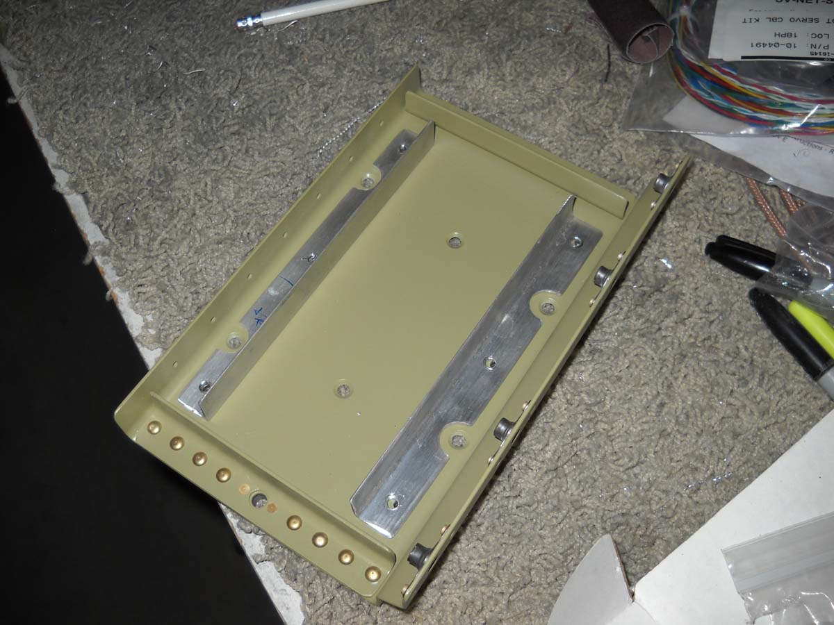
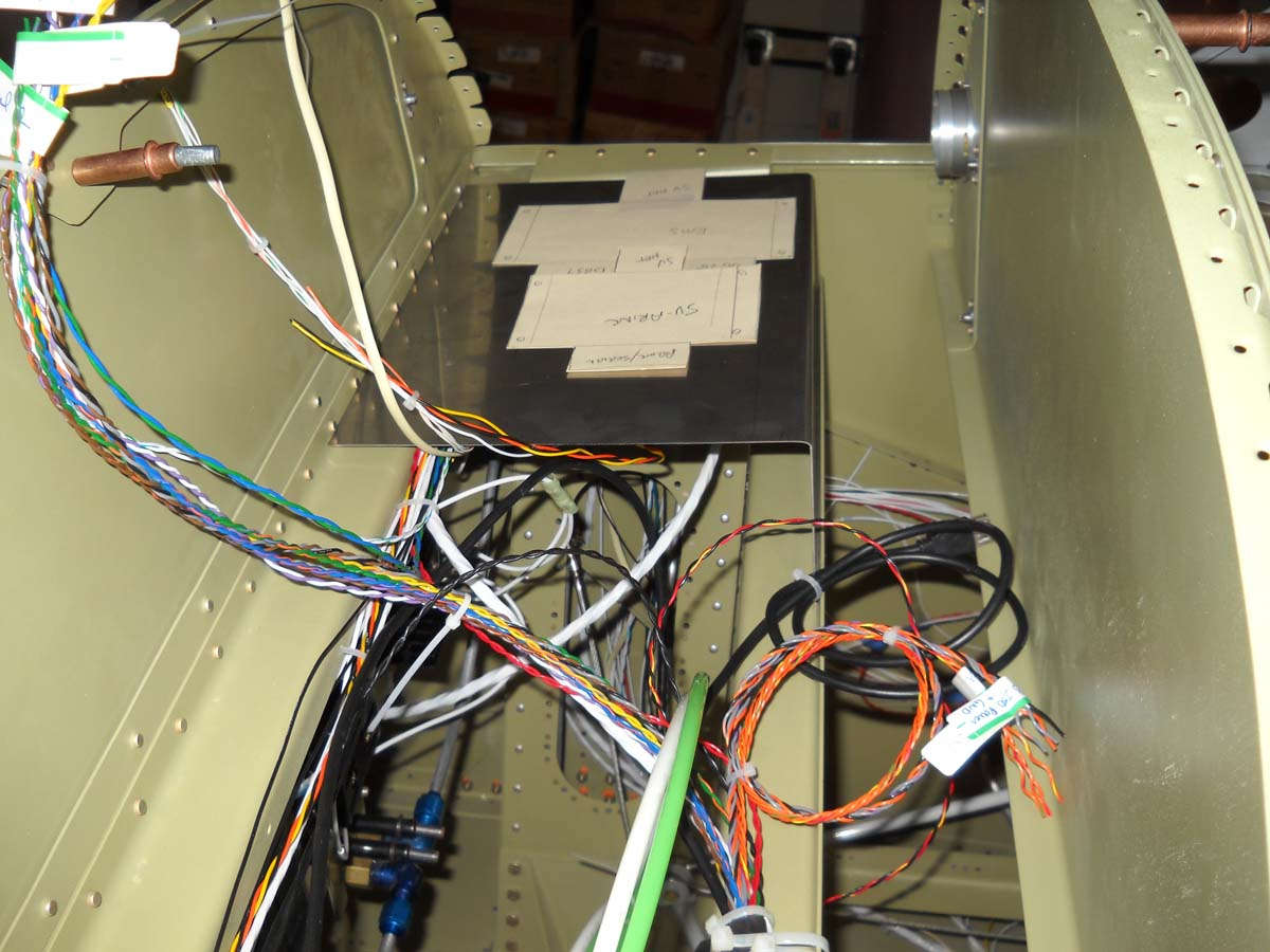
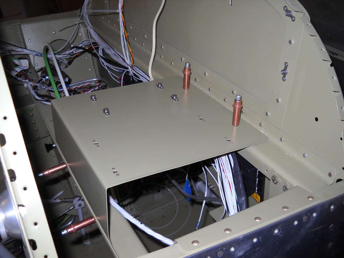
And here is the progress on the shelf I fabricated that will sit behind the instrument panel. It will hold the Skyview EMS module on the upper surface and the ARINC-429 interface module on the lower surface (mounted inverted). This will allow unfettered cable runs for the three EMS wiring harnesses and the two ARINC-429 harnesses. The EMS module is the nerve center of the Skyview engine monitoring system, and the ARINC-429 provides the interface to the Garmin GTN-650 navigator to allow navigation information to be displayed on the Skyview.
This view shows it completed with the priming and the installation of nut plates to accept the two modules.
And here is where it will sit on the right side of the fuselage between the panel and the aft baggage bulkhead. Good place for it because it allows adequate clearance behind the panel for the Skyview 10-inch display and also the deep GTN-650 mounting tray that will go on the left side of the panel. If thing works out okay, this shelf will also hold the Skyview backup battery and ACK-406 ELT monitoring module. Fini.
On to the bulkhead work. I am installing two instrument panel vents for fresh air/heated air to the cockpit, with one on each side of the panel. To bring the hot air in, I deviated from the Van's plans, which basically installs a heat manifold that dumps hot air heated by engine exhaust into the cockpit at the pilot's feet. I purchased this heater valve instead that mounts on the firewall. It is a two part piece, one forward and one aft. When I received the part from Aircraft Spruce and fitted it, I found there is major problem on the aft side in that there is a structural piece of angle that does not allow the part to fit. The solution was to cut the part down to size and then rivet it into position on the end near the structural angle. Thus, I cut it in half which seems to work out okay. Not sure how others have done this because I was following along behind others that have done the same thing. I know some guys have moved this valve and the hole required around on the firewall but I see no need to do this.
Another view of the two parts, the one on the left to be mounted on the aft side of the firewall, the one on the right on the forward side.
Here is the valve in position on the firewall. I had to buy some stainless steel hardware to mount it here, and plan to use a single cable to 1) modulate a valve on the cold air NACA vent and 2) modulate the valve on this heater box. My plan is to pull my control handle and close the incoming cold air and open the incoming hot air to allow temperature control. Again, this is not my idea but another copied one. The internet is a wonderful thing, as are RV-8 builders who have gone before me.
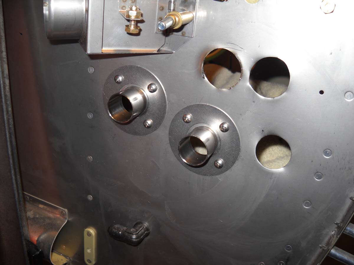
This view also shows my initial planning for the firewall pass throughs. The paper cutouts are three pass throughs for the throttle, propeller, and mixture cables positioned to accommodate the space required. The two doughnut looking markings to their left and below the valve could be the two electric wiring pass throughs. I am using the SafeAir 1 components. Again, some guys move these around on the firewall and I can't really see why unless you have a forward mounted battery, which I don't. I am planning on leaving the forward baggage compartment intact and this is really the only place these pass throughs will work if you do this.
Another view. The big white cable on the right is from the battery and will move to one of the new pass throughs, and the hole the cable comes through right now will probably be used for the cable that will control the heater valve. More to follow here as I try this out for size.
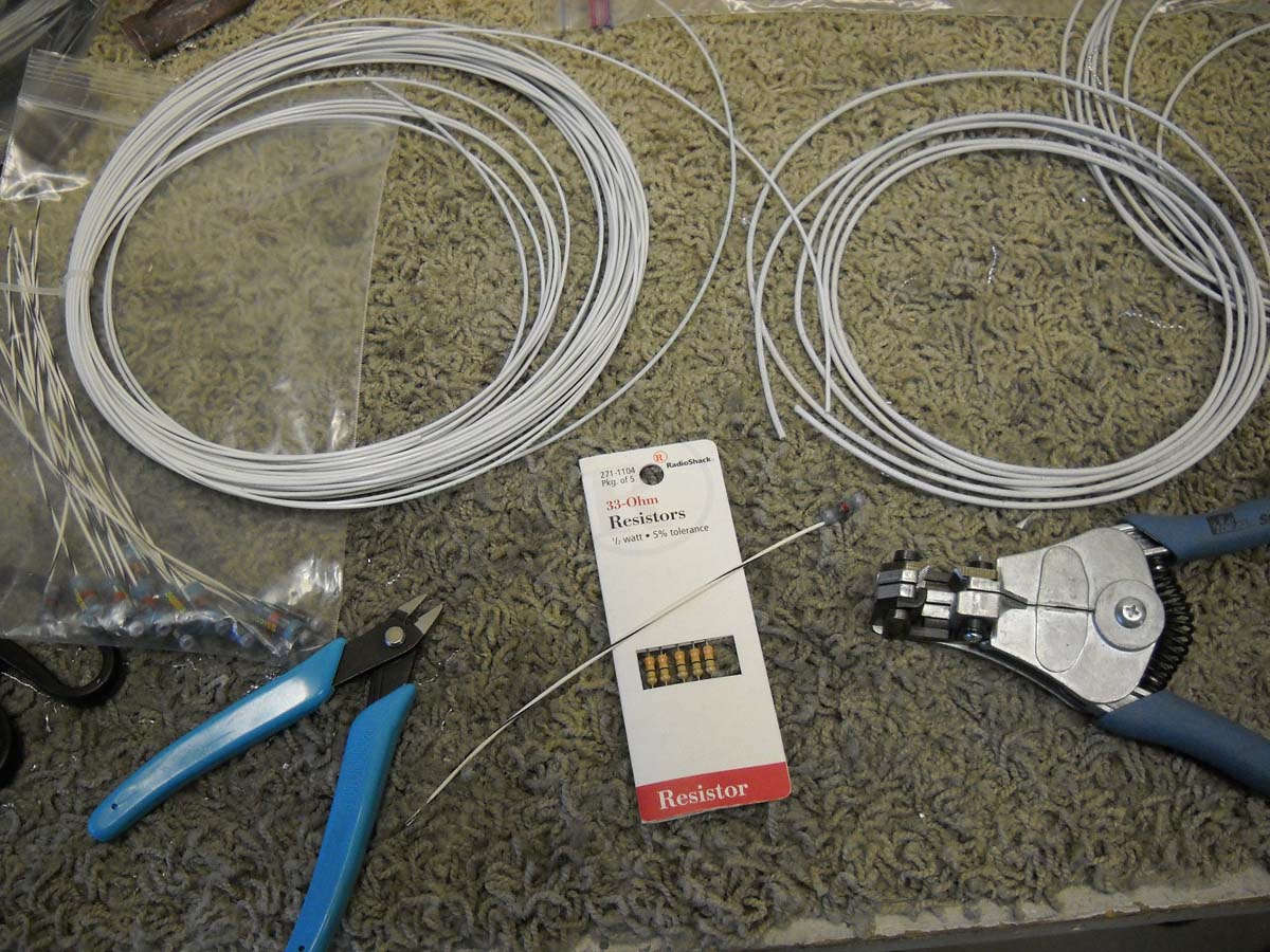
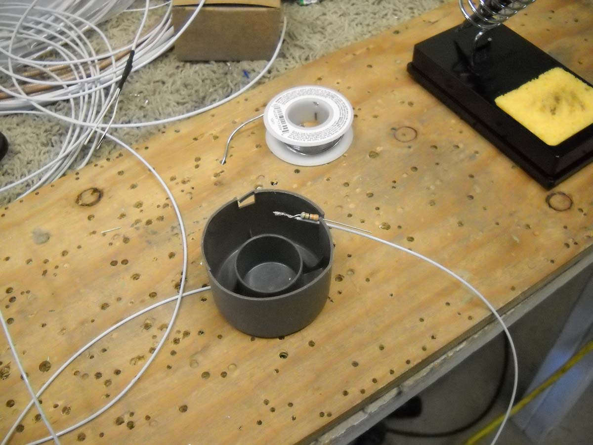
On to fabricating P-Leads for the magnetos, and the accompanying engine RPM pick-offs for the EMS system. Basically what we have is 20 AWG single conductor shielded wire that will be used for the P-Leads. For those not familiar with P-Lead on conventional magnetos (and I was not until recently), these are the wires that ground the magneto to make them little but hunks of metal and not capable of firing spark plugs with the slightest movement. You want the magnetos out of service when the switches are off, so the magneto is grounded through the magneto switch in the cockpit back to the wire shield which is grounded to the magneto. Thus, when the magneto switch is off the grounding circuit is completed.
To add to this, as per the Dynon EMS instructions, I am using 20 AWG unshield wire to connect the P-Lead electric impulses available when the magnetos are live to provide an engine RPM input into the EMS. To reduce the impulses to a acceptable level resistors are added to the circuit between the P-Lead pick off and the EMS. I can barely spell resistor but I can read directions.
For the P-Leads, I stripped the outer insulation off to reveal the wire braid shield. I then cut this back to maybe a 1/4 inch available braid. This allowed me to install a solder shield with an attached wire over the exposed braid to provide a sold connection from the shielding to the attached wire.
So here is the result. One of the wires coming out of the heat shrink is the grounding wire to the shield (braid) and the other is the 20 AWG conductor wire. These ends will be attached to the magneto switches in the cockpit; the other end will be attached to the magneto. Two magnetos, two P-Leads.
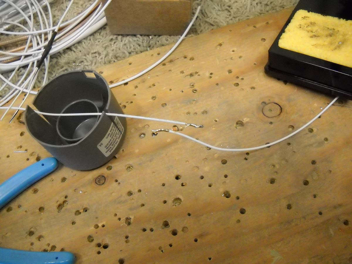
Now, for the engine RPM pick off for the EMS, I prepare to solder the resistors inline on each of two wires. A master soldering person I am not, but with the help of Radio Shack and the EAA Hombuilder Hints online videos, here we go. The proper sized resistor is being soldered to one of the wire leads.
And here the resistor is soldered in line on the wire. The EAA Hombuilder Hint was to solder them in this arrangement to add strength to the connection in that the resistor has no stress placed upon it. When heat shrink is added, the wires are carrying the entire load and the resistor is along for the ride just resisting, I guess, electrons. It's all smoke and mirrors as far as I can tell; I just follow directions.
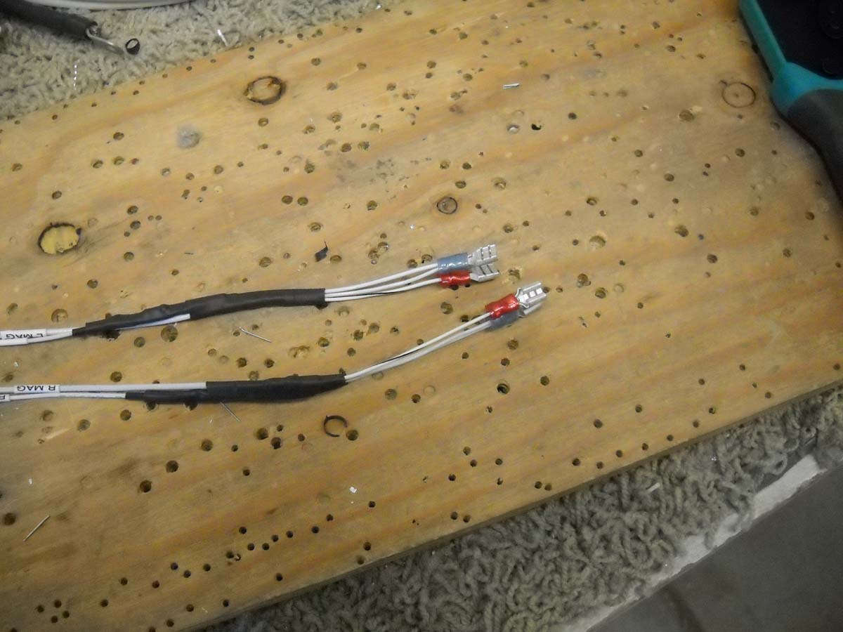
End product is the P-Leads and the RPM pick-offs all ship shape with heat shrink. The P-Lead and RPM pick-offs share one terminal (blue) and the P-Lead ground gets its own (red). These will be connected, again, to the cockpit magneto switches soon enough.
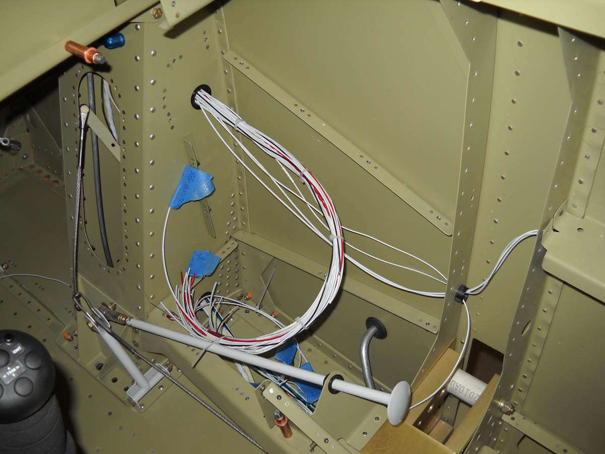
Here is the building wiring bundle that is about ready to be connected to the cockpit switch panel/circuit breaker panel. I need to do a bit more work on that panel to move some things around and also add some lighting controls to it, but it will be installed here in the near future. Wiring aft of the instrument panel is just about done, save one or two wires like the OAT sensor that I don't have and won't have until I buy some black boxes from Dynon.
And, as a follow up, I also finished the vent mount for the aft cockpit and it now installed and ready to accept the SCAT tubing. This vent provides only ambient air (from the NACA vent in the wing) so I used a Steinair vent that completely closes here so that air flow source can be turned off if desired.
So, a couple of weeks of work and I continue to make slow but steady progress.
March 4, 2013
More work on the electrical system, with an emphasis on fleshing out the last major parts of the wiring and working on the firewall pass throughs for both the wiring and engine control cables.
I had earlier decided to pretty much stick with the Van's plans for running the engine controls and the wiring through the firewall, that is, on the lower left side of the firewall while looking forward. I had to increase the diameter of the two engine control cable holes to 1 1/8 inch and add a third engine control cable hole (throttle, mixture, propeller controls) and add two more 1 1/8 inch diameter holes for the wire pass throughs.
I did not have a 1 1/8 inch punch so I decided a step drill should do the job. Not. At least for me, the Harbor Freight step drill does not do a good job at stainless steel at any RPM or with any lubricant assistance I tried. The two holes I completed were ugly but ultimately usable.
I finally located a 1 1/8 inch punch that I was able to borrow. Much, much better in the final result. Stainless steel is hard to work with in any case, but putting big holes in it is a real pain. This photo shows four holes: the top two are step drilled, the bottom two are punched, and the fifth hole is being punched on the left under the heater valve.
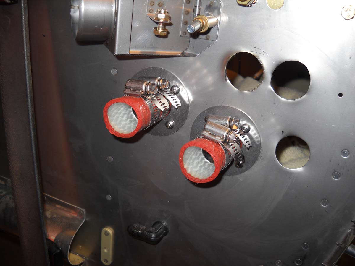
Holes are done and finished. The two SafeAir 1 wiring pass throughs are drilled and mounted in position.
And, the two wiring pass throughs ready for wires. The control cable pass throughs are ready to accept the Doubletree Model 7001 steel eyeballs that are on order.
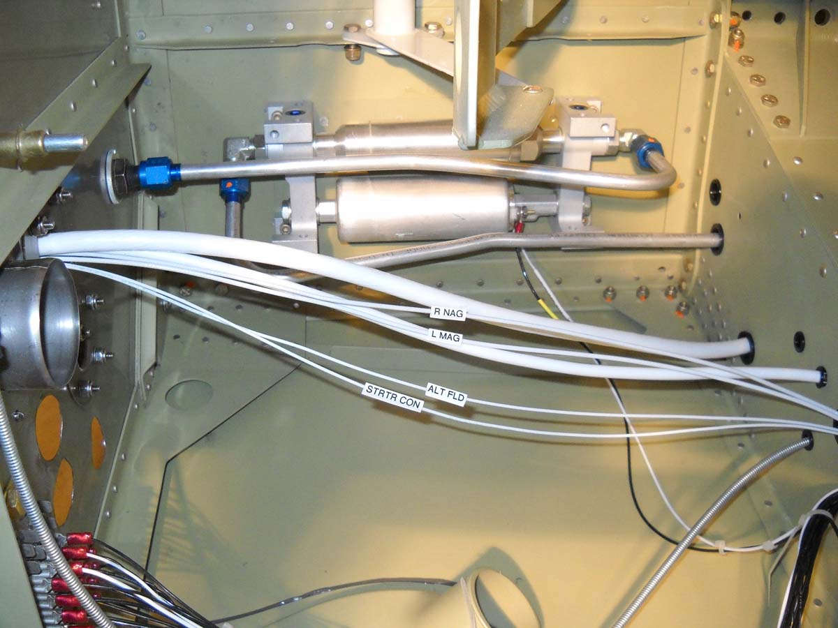
A view of the left forward fuselage looking down toward the fuel pump with some of the wiring going forward through the firewall. Wire labeling is waiting to get heat shrunk onto the wires.
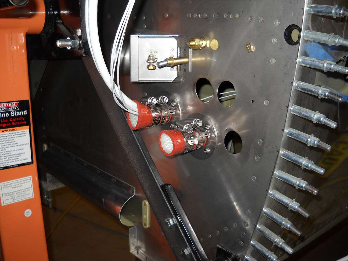
A forward view of the wiring pass throughs with the battery and other wires penetrating.
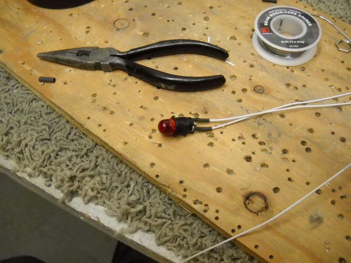
I will have three warning/informational annunciators on the instrument panel: an alternator fault light, an EMS fault light, and a starter engaged light. The first two are red, the last one yellow. Here I am soldering on leads to one of the lights prior to installation on the panel.
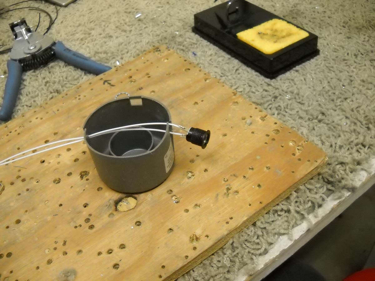
And here it is ready to be mounted and wires run.
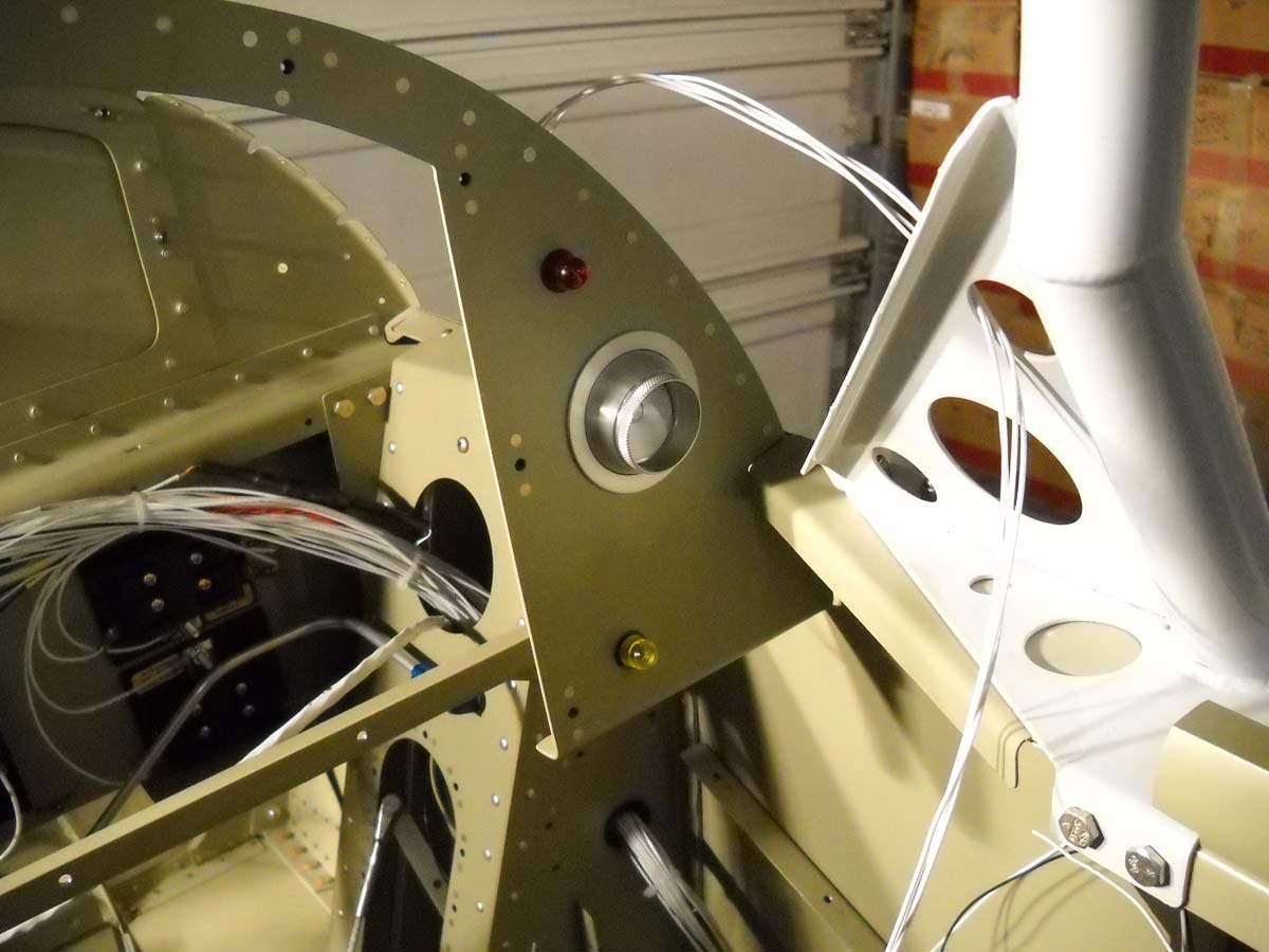
You can pick out the alternator fault red light and started engaged yellow light here on the right side of the panel. A placard marking will be added to each. The started light will be in plain view next to the starter switch. These lights are not absolutely needed but both are easy to install and both the starter contactor and alternator already have provisions for them.
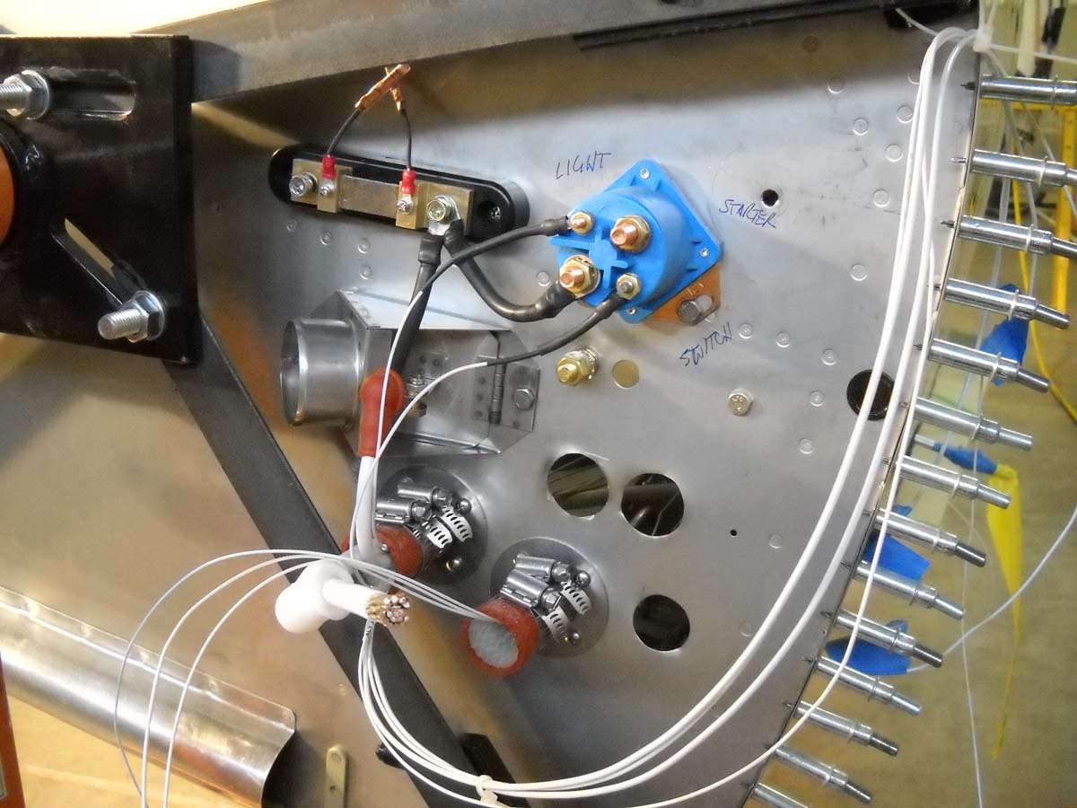
A final view of the firewall for the week with the B&C brand starter contactor (blue case) mounted on the firewall, with the Dynon shunt mounted adjacent to it. The shunt will provide an electrical system sensor input to the Dynon EMS. I used 6 AWG wire between the two, with heat shrink added for protection. The wires that someday will go from the shunt to the current limiter to the alternator will also be 6 AWG.
On the shunt, the two pigtail wires going up from the shunt are fusible links I made out of 26 AWG wire to protect the EMS. These will be mounted downwards and connect to the EMS via 22 AWG wires that can be seen emerging from the pass through on the right. Still need to crimp on the connector for the 2 AWG battery wire before it is connected to the contactor. The two small terminals on the contactor have the starter switch wire and starter engaged light wire attached. The empty terminal will go to the starter motor when it is later installed.
Coming in short order: all the firewall forward EMS wiring will be installed so I can complete the wiring behind the panel. Also, the headset shielded wires will be installed with jacks at one end and the other end positioned for the eventual location of the audio panel. Finally, the switch and circuit breaker panel, already constructed, needs to be modified a bit and then it will be installed. After all that, I will do some wiring checks to make sure all is hooked up properly, or at least what I think is properly right now.
March 19, 2013
More work on the electrical system, finalizing the configuration of the wiring and the systems that it ties together.
The Dynon EMS harness was wired in, including the myriad of ties to the engine sensors monitored by the EMS. I completed the pass throughs of the EMS wiring and is seen here with the other wiring forward of the firewall.
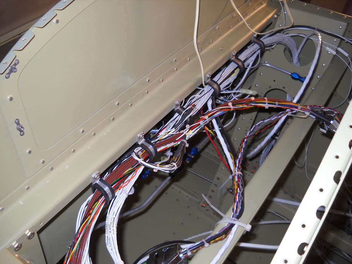
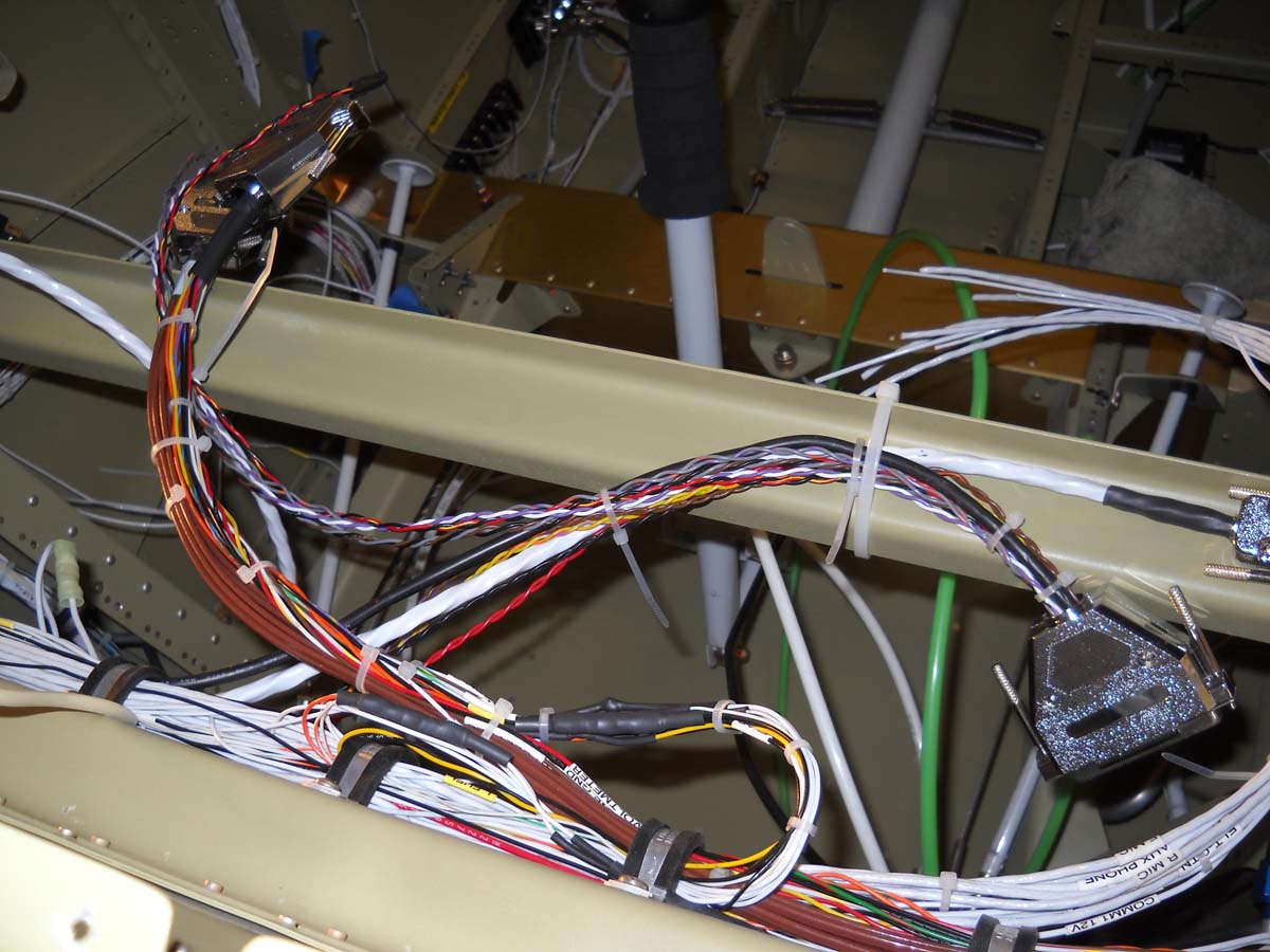
Here is the current state of the wiring behind what will be the instrument panel. Wiring comes up and goes down on each side through the landing gear towers and is linked to fuse panels and connectors. The wiring in this area is just about completed now.
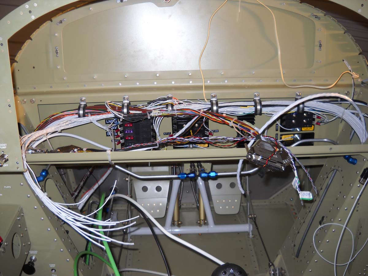
Another view. There are three Dynon connectors here plus several Dynon network connectors plus wires pulled for the GTN-650, the second comm radio, and the audio panel.
The two Dynon EMS connectors are on the left, with the main Skyview display connector on the right. The wires looping around the display connector will eventually be wired into the other panel avionics (audio panel, GTN-650, and second comm radio).
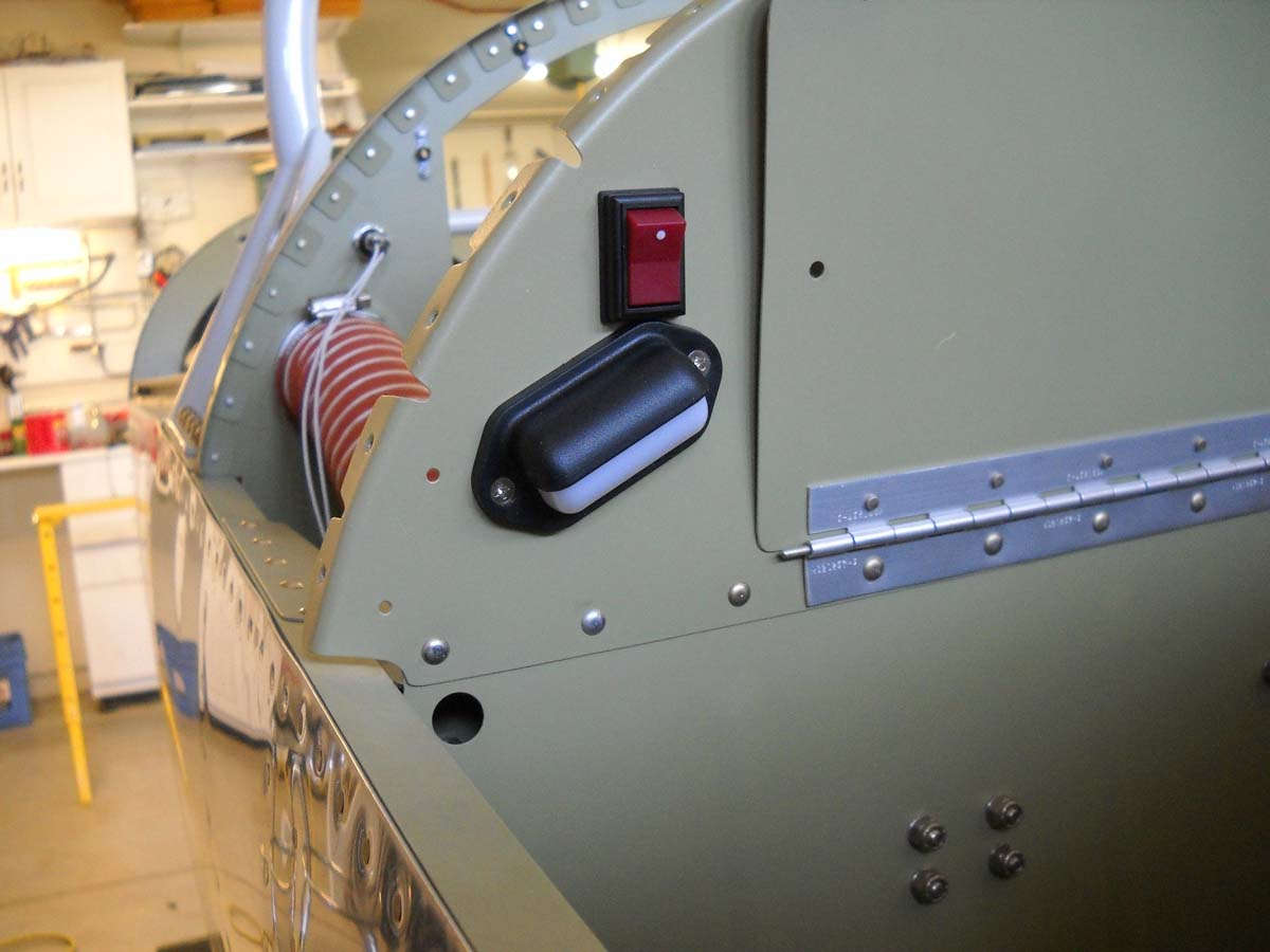
Part of the process of finishing the wiring, here I am wiring in an 12 volt aux power connector into the aft cockpit (turned sideways). The hole is being punched into the arm rest to accept the connector. To the right of the hole on the other panel is the mounted map light dimmer switch and the two headset jacks, one for audio and the other the mic.
Here is the installed 12 volt aux power connector completed.
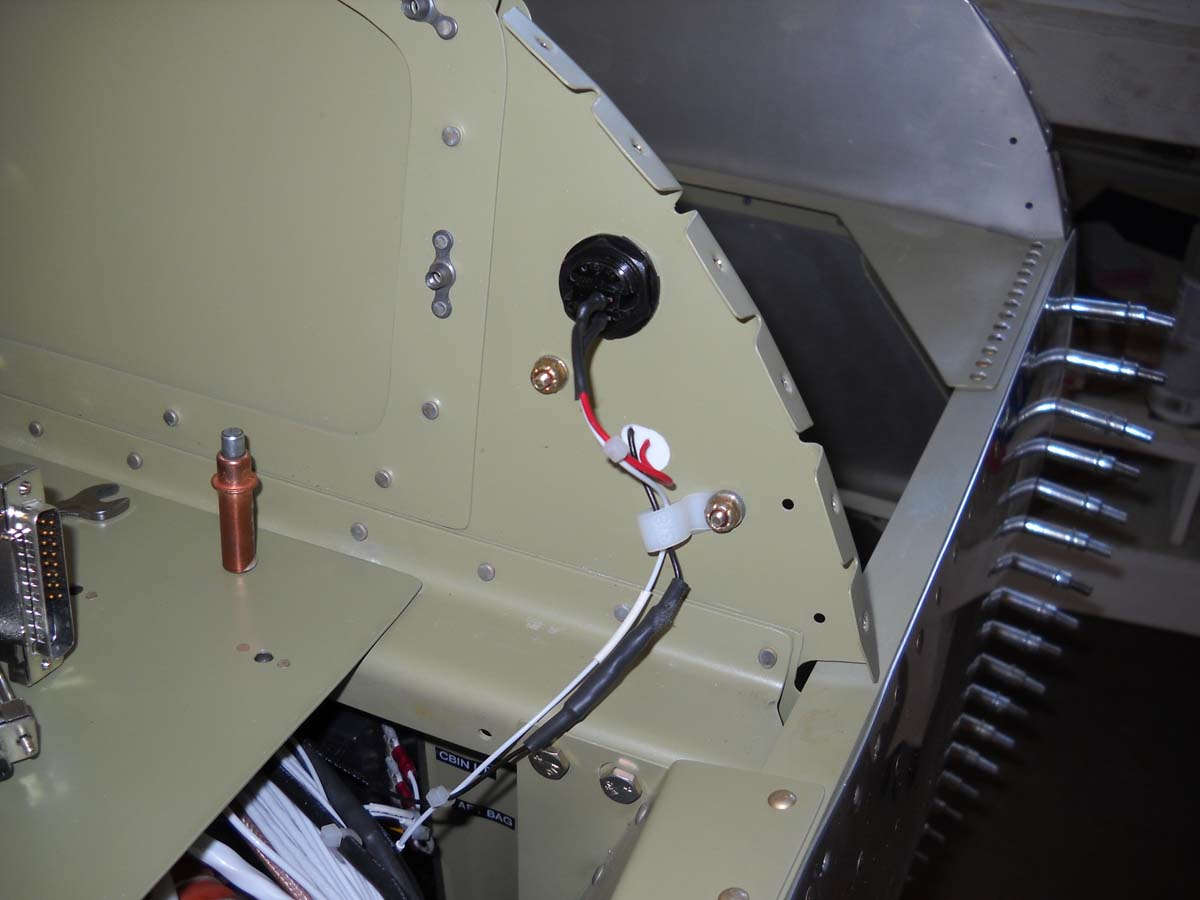
Here is a view of the two headset jacks for the front cockpit (still sideways) installed on the aft side of the center section bulkhead near the top of the fuselage side. Should work just fine there. It took a fair amount of research to get the wiring correct on these jacks. Three wire shielded cable was used to run to the audio panel, and the mic jack had the push-to-talk grounding wire from the control stick wired in also.
I scratched my head a bit trying to figure out how to secure the wiring bundle coming up from each gear tower to the area behind the panel. This was my solution: a piece of angle aluminum cut to size and used to mount an appropriate Adel clamp to secure the bundle. I was just fitting the angle, intending to prime it and then install but it was such a pain to get it into position I might just leave it installed and unprimed right like it is.
The pair of wires going off to the upper right are for the forward baggage compartment light. Like I said, I thought long and hard and think just about all the wiring is in place now, including switches.
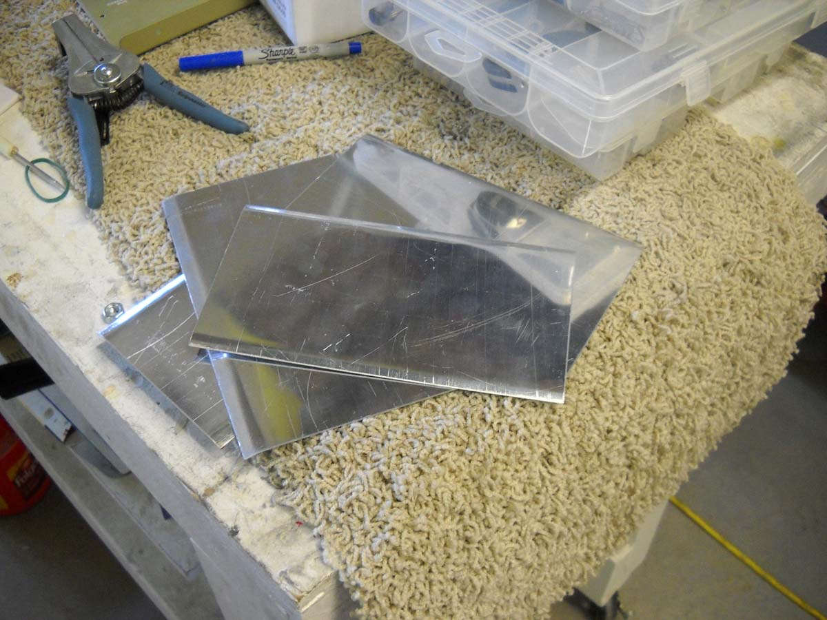
Finally, here are the four pieces of aluminum stock cut for use as antenna doublers. They need to be finished, fitted, and drilled for the antenna and rivets that will hold them to the interior fuselage bottom skin.
I hope to do that prep work next Saturday and finalize the doublers also, at least to the point where they can be primed and set aside for installation.
Also, I plan on making some changes to the circuit breaker panel that will require a bit of work. Once that is done, it will be reassembled and fitted with the switch panel into position and the wires attached to the switches and circuit breakers. At some point after that, I plan to do an extensive continuity check of wiring, breakers, and switches.
April 2, 2013
Moving forward, I've worked on a bunch of little projects to complete the electrical system and associated stuff.
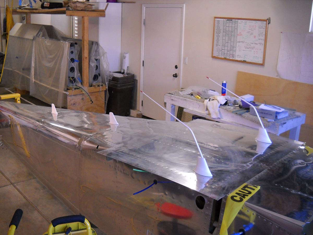
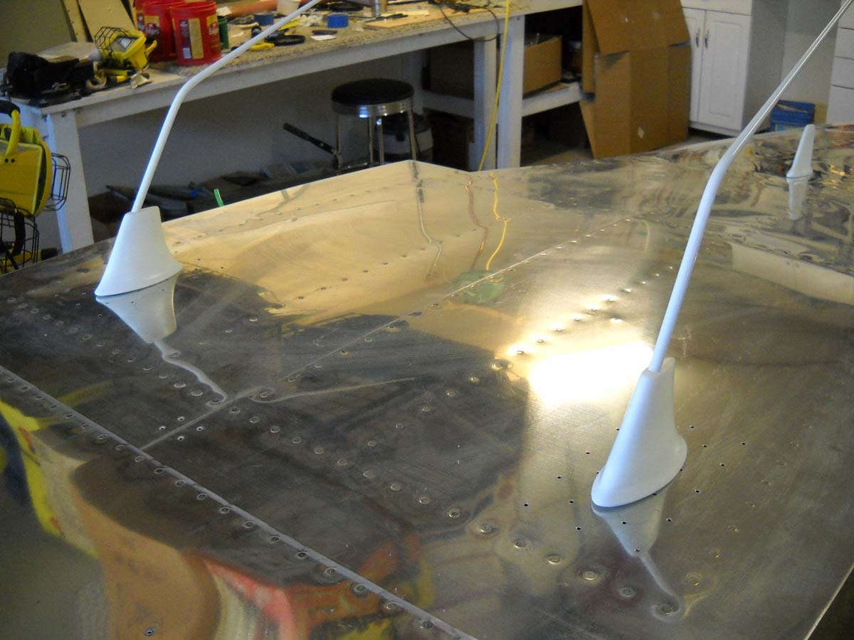
Among those was fabricating the antenna doublers and prepping the antennas for installation. Here are four antennas, two VHF comm antennas and one transponder antenna and one ADS-B antenna. These antennas were all purchased from Delta Pop Aviation based on various recommendations, and are designed for experimental aircraft. The holes are now drilled and the antennas fitted, then put away for future installation once the fuselage is on the landing gear.
Another view of the two VHF comm antennas. I had a bit of a concern here because the GTN-650 installation manual calls for a second comm antenna to be mounted at least six feet from the GTN-650 comm antenna, which clearly is not the case here. However, a number of users have stated that mounting them this close, about two feet separation, has not proven to be a problem on the RV-8. We are betting on their experience.
A view of the inside of the fuselage where, if you look closely, you can see the antenna doubler clecoed into position with the RG-400 coaxial lead laying next to the hole where the antenna will mount.
And here is where the transponder antenna will mount. I considered this for a while on placement and decided this was best. It is slightly off center to eliminate any possible interference with the elevator push rod that is mounted above it.
And, here are the three Doubletree firewall pass through fixtures drilled and riveted into position. These will accept the three engine control cables: throttle, mixture and propeller. I plan on fitting those control cables prior to closing up the forward fuselage just to make the access easy.
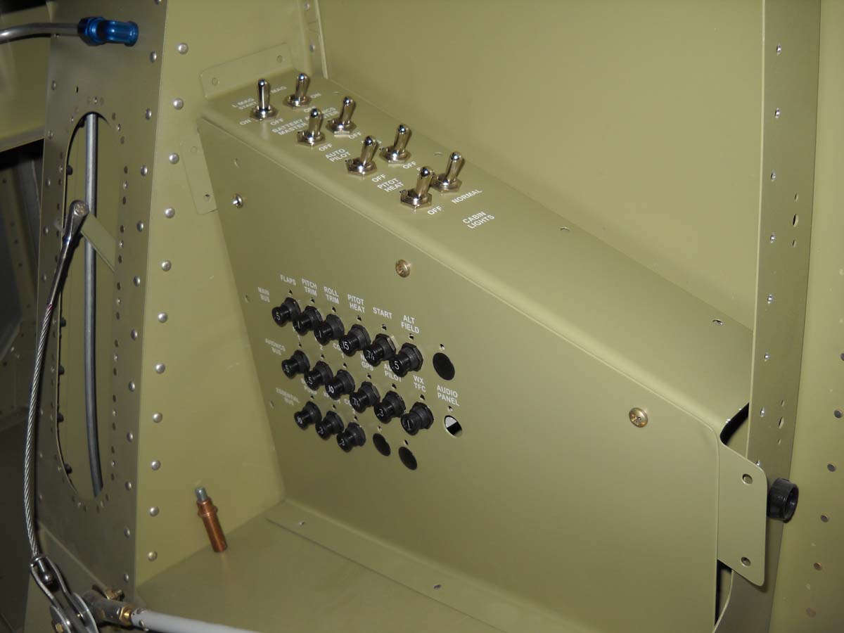
Back again to the circuit breaker and switch panel. I decided earlier to rework the location of two breakers and thus decided to redo the dry transfers that mark the breakers. That work was completed and switch breaker panels reassembled. Also, the panel lighting dimmer switches, an auxiliary music input 1/8" jack, and an auxiliary power recepticle were all installed on the aft portion of the switch panel. At this point I thought I was done and ready for installation.
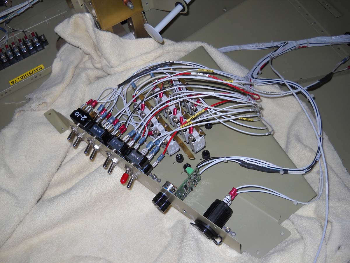
Here is the other side of the breaker and switch panels awaiting the wiring from the airplane to be attached. The magneto/starter switch wiring is such that the starter motor cannot be energized without the left magneto switch being in the momentary "start" position but also that the right magneto switch must be in the "off" position. When I finalized the wiring for this I determined during some continuity checks that I really did not have the correct switch for the right magneto. I need a double throw double pole ON-ON type, so I had to order that for replacement.
While waiting for that switch to arrive, I decided to go ahead and wire in the other connections and replace the magneto switch "in situ," as it were. Here is the wiring from the harnesses attached tot he breakers and panel switches.
And here it all fitted into position, very temporary since I need to replace the right mag switch, and also temporary because it will need to come back out a couple of times for the wing bolts. However, these wires will remain attached and the panel just moved out of the way for future access.
And, I have to point out my cup holder. I purchased the recessed holder from a marine supply store and cut a hole in the panel and epoxied it into position. I think it is a good location and should work out nicely. Just a convenience item but I really haven't seen this on other RV-8s. It seems a natural place for a cupholder. Go nature.
A wider view of the lower forward cockpit in its current state and getting close to its final state.
I was able to purchase a used but unused heated pitot tube/AOA sensor and control box for a bit of a discount from the Dynon offering, so it arrived in good shape and will be set aside for awhile for future installation.
April 16, 2013
In the last few sessions this past week I wrapped up the fabrication of the electrical system, a major milestone in my mind (anyways), and also did some quality control work prior to closing up the front of the fuselage.
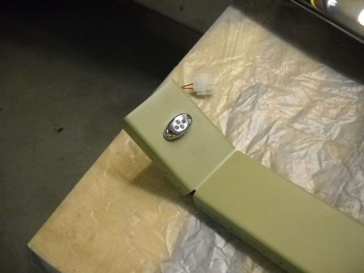
I installed this LED baggage light while I still had good access. It was only later that I realized that this might interfere with the baggage door part that accepts the latch pin. That part mounts in the two holes to the left of the light. We should be able to make it work.
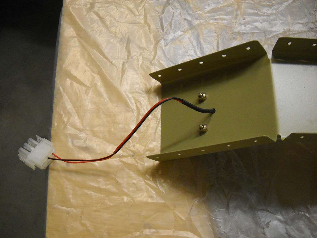
And the back side of that forward baggage area LED light.
I spent an hour or two checking continuity and circuit logic and found more errors than I care to admit to. There were a couple of what I thought were errors also before I figured out that I had to disconnect the 2 AWG battery wire from the starter contactor to isolate the airplane circuits or else they would get power backwards through the wiring. This fact eluded me for a while but after I figured it out the circuits worked pretty much as advertised except for a few glitches, soon enough corrected.
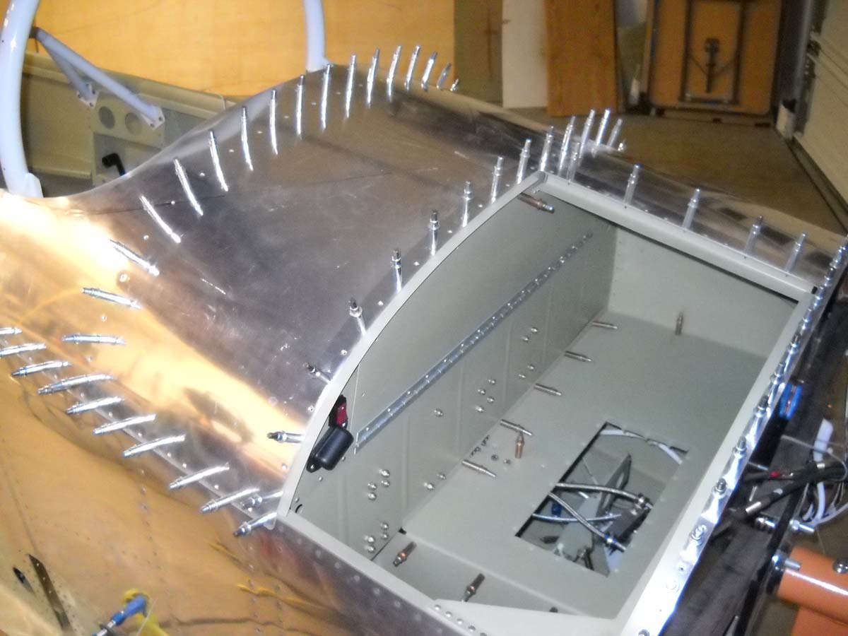
Finally, I thin clecoed on the forward skin in preparation for riveting it into position in the near future.
Another view of the forward fuselage with the upper skin in position.
And, one more.
So, in my mind, I am turning another page in this building project. With the electrical system completed and the forward fuselage closed up, I will turn my attention to attaching the windscreen and doing the fiberglass work for the frame around the windscreen. Something different and, no doubt, more challenges.
November 30, 2013
Not too much in the past few weeks. However, I've done a bit of final wiring in the fuselage. I had previously wired two convenience lights, one in the forward baggage compartment and one in the aft. They are wired to the hot battery bus so the battery master switch does not need to be on for them to work. I had made provisions for a similar cockpit light and completed the wiring on this yesterday. Basically a simple LED light, a Radio Shack push button switch, and a Molex connector. I added the connector because of how the light is mounted. I can disconnect if need be.